RTL to GDSII
1.0.0
Openroad是半导体数字设计的主要开源,基础应用。 OpenRoad流提供了自动驾驶,无人间的(NHIL)流量,从RTL-GDSII进行了24小时的周转,以快速设计探索和物理设计实现。
  Title:
  RTL-GDSII flow Using OpenROAD
   ____________________________________________________
  |  ->Synthesis                                       |
  |      : Inputs  [RTL, SDC, .lib, .lef]              |
  |      : Logic Synthesis  (Yosys)                    |
  |      : Output files  [Netlist, SDC]                |
  |  ->Floorplan                                       |
  |      : Floorplan Initialization                    |
  |      : IO placement  (random)                      |
  |      : Timing-driven mixed-size placement          |
  |      : Macro placement                             |
  |      : Tapcell and welltie insertion               |
  |      : PDN generation                              |
  |  ->Placement                                       |
  |      : Global placement without placed IOs         |
  |      : IO placement  (optimized)                   |
  |      : Global placement with placed IOs            |
  |      : Resizing and buffering                      |
  |      : Detailed placement                          |
  |  ->CTS : Clock Tree Synthesis                      |
  |      : Timing optimization                         |
  |      : Filler cell insertion                       |
  |  ->Routing                                         |
  |      : Global Routing                              |
  |      : Detailed Routing                            |
  |  ->Finishing                                       |
  |      : Metal Fill insertion                        |
  |      : Signoff timing report                       |
  |      : Generate GDSII  (KLayout)                   |
  |      : DRC/LVS check (KLayout)                     |
  |____________________________________________________|
 sudo apt-get update
sudo apt - get update
sudo apt - get install gperf
sudo apt - get install autoconf
sudo apt - get install gcc g ++
sudo apt - get install flex
sudo apt - get install bison
 wget https://github.com/steveicarus/iverilog/archive/refs/tags/v12_0.tar.gz

tar -xvzf v12_0.tar.gz

cd iverilog-12_0
sh autoconf.sh
./configure

sudo make
sudo make install
测试安装:在终端中写入“ iverilog”,然后按Enter成功安装应显示以下输出:iverilog:无源文件,建议-c,-y等。
sudo apt install gtkwave
我们将使用GTKWave中的示例来了解如何绘制信号。
 sudo apt update
sudo apt-get install zlib1g-dev
git clone https://git.savannah.gnu.org/git/libiconv.git

sudo apt-get install tcl8.6
sudo apt-get install tcl8.6-dev
sudo apt-get install tk8.6
sudo apt-get install tk8.6-dev
sudo apt-get install doxygen

git clone https://github.com/chiphackers/covered
cd covered
./configure
sudo make
sudo make install
如果“ tcl Interp'没有成员命名”结果'错误:
 cd covered
cd src
gedit report.c
在Report.c文件中,您将看到#include命令的列表。在#include <tcl.h>之前找到#include <tcl.h>,然后添加以下命令'#define use_interp_result 1'。
您的报告看起来像这样:
 #ifdef HAVE TCLTK
#define USE_INTERP_RESULT 1
#include <tcl.h>
保存report.c文件。再次运行Make Command,然后继续进行安装过程,如上所示。
来源Verilog代码:
// 4 bit synchronous counter
module Mycounter (CLK, RST , OUT );
 input CLK, RST;
 output [3:0] OUT ;
 reg [3:0] OUT;

 always @( posedge CLK )
 begin
 if (RST == 1'b1 )
    OUT <= 4'b0000 ;
 else
    OUT <=OUT+1;
 end
endmodule
TestBench Verilog代码:
// Testbench for a 4 bit synchronous counter
module Testbench ();
reg Clock , Reset ;
wire [3:0] Count ;

// instantiate the DUV and make connections
Mycounter I1(.CLK ( Clock ),. RST ( Reset ),.OUT( Count ) );

// initialize the Testbench
initial begin
$display (" Starting simulation ...");
Clock = 1'b0 ;
Reset = 1'b1 ; // reset the counter at t=0
# 100 Reset = 1'b0 ; // remove reset at t=100
# 2000 Reset = 1'b1 ; // remove reset at t= 2100
# 400 $finish ; // end the simulation after t= 2500
end

// generate stimulus (in this case clock signal )
always #50 Clock =∼Clock ;// clock period =100

// monitor the response and save it in a file

initial begin
$dumpfile ("count.vcd"); // specifies the VCD file
$dumpvars ; // dump all the variables
$monitor ("%d ,%b ,%b ,%d", $time , Clock , Reset , Count );
 end
endmodule
•启动Linux发行版并制作目录$ mkdir icarus_codes
伊卡洛斯代码是目录的名称。
•将目录更改为Icarus代码。为了进行仿真,您需要一个用于实现功能的Verilog代码和.v格式的测试工作台。在工作目录中包括那些。假设我的Verilog代码名为Mycounter.v ,testbench是Testbench.v 。模拟:
 $ iverilog -o Mycounter Mycounter.v Testbench.v
$ vvp Mycounter
创建了一个我称为Count.VCD的转储文件,也是创建的,您也可以在终端上看到输出。您还可以查看GTKWAVE中的输出
$ gtkwave count.vcd此命令启动gtkwave Analyzer应用程序。在左图中,展开测试台,然后单击子文件夹。它将扩展以显示输入时钟,重置和输出波形[3:0]。将它们拖到信号面板上并分析结果。
为了估计测试工作台测试的RTL设计的百分比,使用了覆盖的Verilog代码覆盖分析仪工具。 •通过执行以下命令在同一目录中生成代码覆盖报告,ICARUS代码
$ covered score -t Testbench -v Testbench.v -v Mycounter.v -vcd count.vcd -o Mycounter.cdd
•要查看覆盖报告,请执行
$ covered report -d v Mycounter.cdd
覆盖范围报告显示在终端中。
如果遇到任何称为“分段故障”的错误,请尝试以下操作:
sudo apt-get install gedit
在GEDIT中打开生成的VCD文件,找到“ $注释显示参数值。$ end”并删除它。
保存VCD文件,然后Agin运行流,现在应该工作。
sudo apt-get install -y build-essential clang bison flex libreadline-dev gawk tcl-dev libffi-dev git graphviz xdot pkg-config python3 libboost-system-dev libboost-python-dev libboost-filesystem-dev zlib1g-dev
 git clone https://github.com/YosysHQ/yosys.git
git submodule update --init
cd yosys
sudo make
sudo make install
安装后尝试调用yosys,例如: ./yosys the工具启动,命令提示符更改为yosys>
在这里,我给了名为Nangate45_typ.lib的库文件
要使用yosys合成任何Verilog源文件,必须将此库文件包含在TCL自动化脚本中。
制作一个名为yosys_commands.tcl的文件,然后将此行放入文件中并保存。
 #Read modules from verilog
read_verilog counter.v

#Elaborate design hierarchy
hierarchy −check −top Mycounter

#Translate Processes to netlist
proc

#mapping to the internal cell library
techmap

#mapping flip-flops to Nangate45_typ.lib
dfflibmap −liberty Nangate45_typ.lib

#mapping logic to Nangate45_typ.lib
abc -liberty Nangate45_typ.lib

#remove unused cells
clean

#write the synthesized design in a verilog file
write_verilog −noattr synth_Mycounter.v
调用Yosys之后,应运行此TCL脚本。这将自动化合成过程并从源Verilog文件中编写合成的NetList
启动我正在使用yosys_commands.tcl文件的yosys工具$ yosys 。 yosys> script yosys_commands.tcl
类似地,运行给定的not_opt.tcl和opt.tcl脚本,用于查看非优化的框图和优化的框图(xdot)窗口中的优化框图
 sudo apt-get update
sudo apt-get install build-essential tcl-dev tk-dev cmake git

git clone https://github.com/The-OpenROAD-Project/OpenSTA.git
cd OpenSTA
mkdir build
cd build
cmake ..
如果错误像Cmake error at CMakelists.txt一样,则使用“ CD”命令移至主目录并安装
sudo apt-get install libeigen3-dev
再次转到OpenSta中的构建目录,并通过执行以下命令来配置构建:
cmake ..
如果再次出现任何CMAKE错误,则再次移至Home Directory并安装CUDD。
 git clone https://github.com/ivmai/cudd.git
sudo apt-get install automake
sudo apt-get install autoconf m4 perl

cd cudd
autoreconf -i
mkdir build
cd build
../configure --prefix=$HOME/cudd
sudo make
sudo make install
现在,CUDD已成功安装。现在移至OpenSta目录
 cd OpenSTA
cd build
cmake .. -DUSE_CUDD=ON -DCUDD_DIR=$HOME/cudd
sudo make
sudo make install
现在,只需键入“ sta”,然后按Enter将其更改为
 sta [~/working_directory]

or,
it will be shown like

%
在成功安装OpenSta之后,将time.tcl运行以分析输入和输出的时间,然后运行power.tcl以通过设计的电路分析功率耗散。
用于使用OpenSTA的时间分析
% source time.tcl
用于使用OpenSTA的功率分析
% source power.tcl
下载OpenRoad存储库
 git clone --recursive https://github.com/The-OpenROAD-Project/OpenROAD.git
cd OpenROAD
安装依赖项
sudo ./etc/DependencyInstaller.sh
建立公开
 mkdir build
cd build
cmake ..
sudo make
sudo make install
如果运行“ cmake”后,则显示错误: CMake Error: Could not find CMAKE_ROOT !!!然后运行export PATH=/usr/local/bin/cmake:$PATH并运行echo $CMAKE_ROOT ,它应该反映路径,然后重新运行“ cmake”和agin run“ make&make install”
如果仍然发生任何错误:
 sudo apt install swig
sudo apt update
从终端调用OpenRoad工具,应将其更改为openroad>
用于执行活动的脚本:
design_nangate45.tcl
 1. RTL Netlist: gcd_nangate45.v
(Location: OpenROAD/test/gcd_nangate45.v)
2. SDC file: gcd_nangate45.sdc
(Location: OpenROAD/test/gcd_nangate45.sdc)
3. Library file: Nangate45_typ.lib
(Location: OpenROAD/test/Nangate45/Nangate45_typ.lib)
4. LEF file
A. Technology Lef: Nangate45_tech.lef
(Location: OpenROAD/test/Nangate45/Nangate45_tech.lef)
B. Standard Cell Lef: Nangate45_stdcell.lef
(Location: OpenROAD/test/Nangate45/Nangate45_stdcell.lef)
写design_nangate45.tcl文件
 source "helpers.tcl"
source "flow_helpers.tcl"
source "Nangate45/Nangate45.vars"
set design "<design name>"
set top_module "<design main module>"
set synth_verilog "synth_design.v"
set sdc_file "top.sdc"
set die_area {0 0 100.13 100.8}
set core_area {10.07 11.2 90.25 91}
source -echo "flow.tcl”
现在所有文件都准备就绪,一些特定文件需要复制到“ OpenRoad/Test”文件夹中,这是:
 design.v
synth_design.v
top.sdc
design_nangate45.tcl
将此文件复制到OpenROAD/test文件夹后,转到同一目录并调用OpenRoad以将文件从一个目录复制到另一个目录是:
sudo cp -i /path/of/your/directory/<filename> /path/to/directory/to/copy/
然后
openroad> sudo openroad -gui -log design_logfile.log design_nangate45.tcl
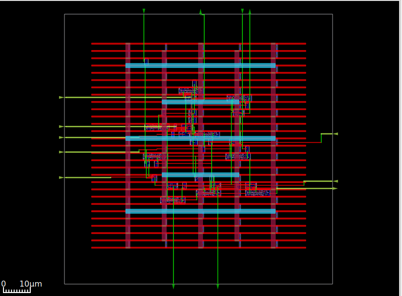
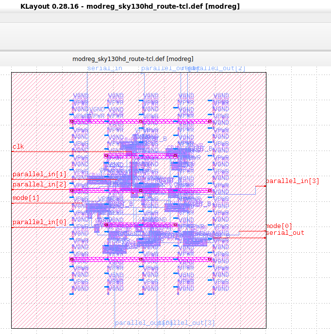
运行此命令将生成ASIC布局,该布局将在OpenRoad GUI中可见,以将其保存为GDSII,它需要Klayout。
sudo apt install klayout
使用此命令打开klayout
klayout &
现在单击“文件”按钮,然后选择读取器选项,然后单击“ lef/def”选项卡,“ nangate45.lef”文件需要放置并取消选中复选框(如果已检查)或保持“ nangate45.lef”的相同位置
/OpenROAD/test/Nangate45/Nangate45.lef
然后单击确定。在此之后,请再次单击文件并选择“打开”,现在将打开对话框,导航到
/OpenROAD/test/result
design.def文件将找到,单击DEF文件,然后单击“确定”。现在它将以GDSII模式打开,可以保存为GDSII。
现在,设计可以发送到铸造厂进行制造。
 [1] Installation steps for The ICARUS Verilog Compilation System. [Online]. Available:
https://github.com/steveicarus/iverilog

[2] Installation steps for Covered - Verilog Code Coverage Analyzer. [Online]. Available:
https://github.com/chiphackers/covered/blob/master/INSTALL

[3] S. Saurabh, Introduction to VLSI Design Flow. Cambridge: Cambridge University Press,
2023.

[4] Installation steps for Yosys Open SYnthesis Suite. [Online]. Available: https:
//github.com/YosysHQ/yosys

[5] S. Saurabh, Introduction to VLSI Design Flow. Cambridge: Cambridge University Press,
2023.

[6] Yosys: Example Usage. [Online]. Available: https://yosyshq.net/yosys/

[7] Documentation for Yosys Open SYnthesis Suite commands. [Online]. Available:
https://yosyshq.readthedocs.io/projects/yosys/en/manual-rewrite/cmd ref.html

[8] Ajayi, Tutu, Vidya A. Chhabria, Mateus Fogaça, Soheil Hashemi, Abdelrahman Hosny,
Andrew B. Kahng, Minsoo Kim et al. "Toward an open-source digital flow: First learnings
from the openroad project." In Proceedings of the 56th Annual Design Automation
Conference 2019, pp. 1-4. 2019.

[9] Ajayi, Tutu, and David Blaauw. "OpenROAD: Toward a self-driving, open-source digital
layout implementation tool chain." In Proceedings of Government Microcircuit
Applications and Critical Technology Conference. 2019.


