esphome ferraris meter
Release 1.4.1
笔记
这是德语版本,用于英文版本,向下滚动或单击此处。
Ferraris仪表是用于创建ESP固件的杂质组件,它可以使用ESP微控制器和红外传感器来确定模拟法拉利流仪表的转盘的速度和旋转,并且可以从中计算当前的电力消耗和仪表状态。然后可以将这些值发送到家庭自动化软件,例如家庭助理进行进一步处理。
该软件(包括带有硬件样本结构的文档)无需违约,也没有任何明确或默认的保修,包括但不限于保证市场访问,适用于特定目的以及不侵权第三方权利。作者或版权所有者绝不应对索赔,损害或其他义务,无论是在合同或责任诉讼中,未经授权的行为还是其他与软件或使用其他商店有关的法案或其他商店。
仅需要ESP微控制器(例如ESP8266或ESP32,包括电压电源)和红外传感器(例如TCRT5000)。对于法拉利仪表的纯粹功能,ESP8266完全足以作为微控制器。对于红外传感器,具有3.3V-5V输入电压的基于TCRT5000的结束模块,该模块还具有可控的电阻(电位计)来校准数字输出。这些TCRT5000模块具有4个用于传感器芯片电源的PINS-VCC和GND,以及数字输出D0和一个模拟输出A0。
将传感器放在法拉利电流仪表的盖板上时,需要一些技能和精确工作。传感器的红外发射器/接收器夫妇必须在毫米精确的中间对齐,并在转盘上直接指向转盘。
原则上,法拉利仪表组件支持以下开发变体:
要创建Esphome固件,必须创建基于YAML的配置文件。您可以将此存储库中提供的示例配置文件之一用作起点,并根据您的需求进行调整。
原则上,有两种构建Esphome固件的方法:
您应该选择哪种方法取决于您对Esphome的信任程度,以及您是否喜欢使用图形用户界面或命令行使用。此外,构建固件的主机的性能可以发挥加速过程。
笔记
不必复制此存储库(“叉”)并适应复制存储库中的示例配置。取而代之的是,可以保存和调整样本配置或取消主机助理主机上的适应配置(如果需要使用Esphome Device编译器附加组件来创建Esphome固件)。
以下各节描述了固件配置文件中包含的最重要组件。
组件法拉利是必不可少的,必须添加以使用传感器。
由于它是不属于Esphome的自定义组件,因此必须明确导入它。最简单的方法是直接从此存储库中加载组件。
 external_components :
  - source : github://jensrossbach/esphome-ferraris-meter
    components : [ferraris]
提示
在上面的示例中,从存储库的main分支邀请了组件的最新状态。但是,我建议通过版本编号提及发布的支架,以更多地控制使用哪种软件支架,并能够对“破坏更改”做出更好的反应。请参阅示例配置如何完成。
可以配置以下通用设置:
| 选项 | 类型 | 需要 | 标准 | 描述 |
|---|---|---|---|---|
id | ID | 否1 | - | 法拉利组件的实例 |
digital_input | 别针 | 是2 | - | 连接TCRT5000模块的数字输出的GPIO PIN |
analog_input | ID | 是2 | - | ADC传感器读取连接到TCRT5000模块的模拟输出的引脚 |
analog_threshold | 号码 / ID 3 | 不 | 50 | 通过模拟输入检测革命的阈值 |
off_tolerance | 号码 / ID 3 | 不 | 0 | 降落侧面的模拟阈值值负偏移,请参见downings dowmessing soldings“ |
on_tolerance | 号码 / ID 3 | 不 | 0 | 上升侧面的模拟阈值值的积极偏移,请参见downings dowmessing soling soldings详细信息 |
rotations_per_kwh | 数字 | 不 | 75 | 每千瓦时转盘的旋转数量(该值在法拉利电流仪表上注明) |
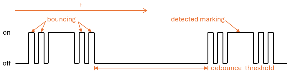
debounce_threshold | 号码 / ID 3 | 不 | 400 | 在跌落和随后的侧面增加之间的毫秒毫秒时,革命被考虑到革命,请参阅部分,请参阅部分 |
energy_start_value | ID | 不 | - | 数字组件的值将启动中的值用作消耗仪的起始值 |
1某些应用程序需要配置元素id 。
2根据硬件开发变体,只需要两个配置元素之一 - digital_input或analog_input 。
3配置元素analog_threshold , off_tolerance , on_tolerance和debounce_threshold期望固定数字或数字组件的ID。后者允许通过用户界面配置该值(例如,使用模板号组件)。
 ferraris :
  id : ferraris_meter
  digital_input : GPIO4
  rotations_per_kwh : 75
  debounce_threshold : 400
energy_start_value : last_energy_value如果要将ESP集成到家庭助理中,则需要API组件。如果要使用替代家庭自动化软件,则必须添加MQTT组件。但是,某些机制(例如重新启动仪表架或重新启动后的最后一个仪表尺度的恢复)(请参阅下面的详细信息),而不再工作。
以下是与家庭助理(和加密API)集成的示例:
 api :
  encryption :
    key : !secret ha_api_key
这是使用MQTT与替代家庭自动化软件一起使用的示例:
 mqtt :
  broker : 10.0.0.2
  username : !secret mqtt_user
password : !secret mqtt_passwordWiFi组件应可用,否则传感器值不能轻易传输到另一个设备。
 wifi :
  ssid : !secret wifi_ssid
password : !secret wifi_password法拉利组件具有主要传感器,可输出计算出的校准模式的消耗值和诊断传感器。所有传感器都是可选的,如果不需要它们,则可以被排除。
可以配置以下主要传感器:
| 传感器 | 类型 | 设备类 | 州类 | 单元 | 描述 |
|---|---|---|---|---|---|
power_consumption | 数值 | power | measurement | w | 当前的功耗 |
energy_meter | 数值 | energy | total_increasing | WH | 总电流消耗(电表/米) |
您可以在Esphome传感器组件的文档中找到有关单个元素的配置选项的详细信息。
 sensor :
  - platform : ferraris
    power_consumption :
      name : Momentanverbrauch
    energy_meter :
name : Verbrauchszähler 可以配置以下诊断传感器:
| 传感器 | 类型 | 描述 |
|---|---|---|
rotation_indicator | 二进制 | 显示转盘上的标记是否仅在红外传感器的前面(仅在校准模式下起作用) |
您可以在Esphome二进制传感器组件的文档中找到有关单个元素的配置选项的详细信息。
 binary_sensor :
  - platform : ferraris
    rotation_indicator :
name : Umdrehungsindikator出于诊断目的,法拉利组件具有开关。它具有名称calibration_mode ,可用于将组件放入校准模式(有关更多信息,请参见部分校准)。
 switch :
  - platform : ferraris
    calibration_mode :
name : Kalibrierungsmodus法拉利组件提供了两个动作,以设置仪表刻度并设置过渡计数器。
| 行动 | 描述 |
|---|---|
ferraris.set_energy_meter | 将仪表状态放在指定值 |
| 范围 | 类型 | 区域 | 描述 |
|---|---|---|---|
value | float | > = 0 | 千瓦时仪表的目标价值(kWh) |
笔记
尽管当前仪表状态的传感器具有WH(瓦小时) ,但覆盖仪表支架的动作使用了单位kWh(千瓦时) ,因为模拟的素素电流仪表通常也显示仪表。
| 行动 | 描述 |
|---|---|
ferraris.set_rotation_counter | 将旋转计数器放在指定的值上 |
笔记
设置仪表架的动作间接设置了旋转柜台,因为法拉利组件内部与旋转局部合作,而不是瓦特小时或千瓦时。
| 范围 | 类型 | 区域 | 描述 |
|---|---|---|---|
value | uint64 | > = 0 | 营业额计数器数量革命的目标值 |
本节描述了法拉利组件的各种应用示例。
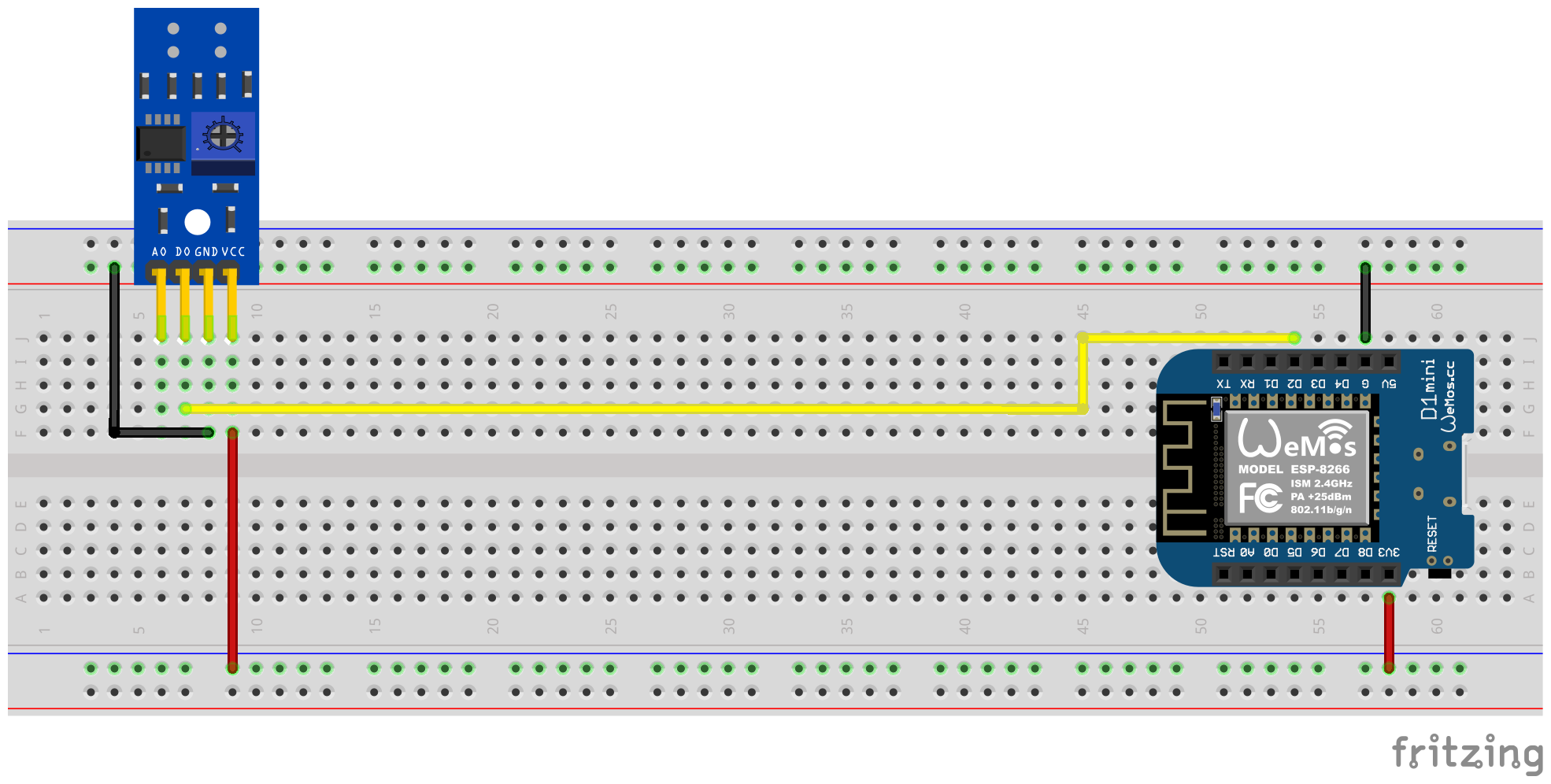
在此变体中,红外传感器的数字输出用于识别转盘的转速。不需要模拟输出,其他引脚必须连接到微控制器的相应引脚。对于VCC,应使用ESP的3.3V输出,并且必须将数字输出D0连接到免费的GPIO引脚(例如GPIO4,对应于D1 Mini上的引脚D2)。
以下插件电路图显示了具有ESP8266 D1 Mini开发板作为微控制器的实验设置的示例。
借助螺丝刀,必须通过电位计对数字输出信号进行校准。传感器背面的两个绿色LED帮助。当传感器提供电力时,右LED会永久发光。只要没有“障碍”在反射被中断时,左led灯光就会闪耀。后者是法拉利电流仪表转盘上的标记在传感器前面徘徊时的条件。因此,应设置电位计,以使左LED在标记不在红外发件人/收件人夫妇的区域中时仍会发光,而标记将其推向前面。这只是一个很小的区域,很难找到此设置。为了提供此过程的额外支持,可以在Ferraris仪表固件中激活校准模式,有关详细信息,请参见校准部分。
提示
如果无法为电位计找到合适的功能设置,则可以使用红外传感器的模拟输出,请参见下一节。
必须在PIN YAML配置文件中为Ferraris组件配置软件端,该文件连接到TCRT5000模块的数字输出:
 ferraris :
  id : ferraris_meter
  digital_input : GPIO4
  # ...
示例配置: ferraris_meter_digital.yaml
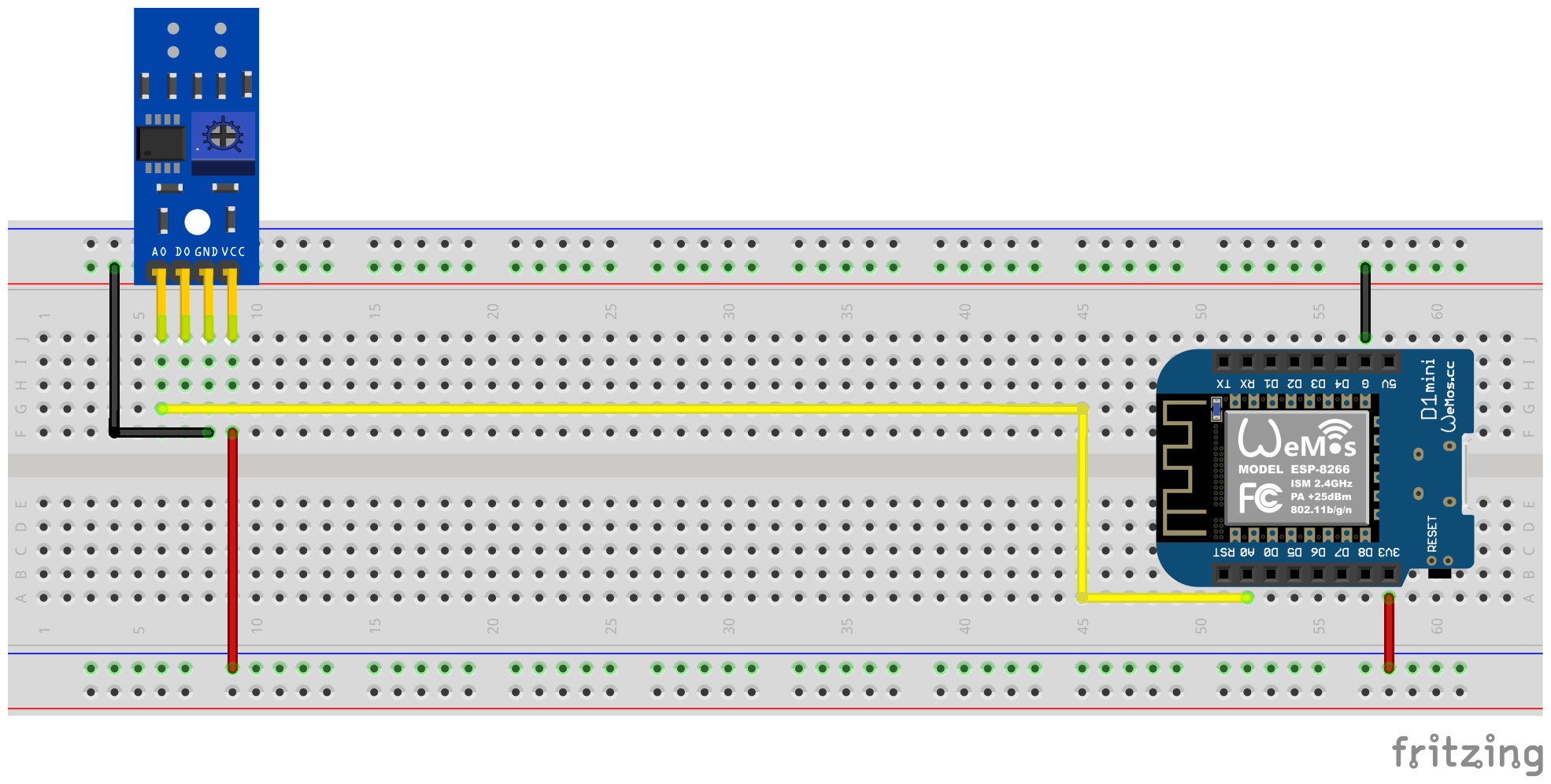
在此变体中,红外传感器的模拟输出用于识别转盘的转速。不需要数字输出,其他引脚必须连接到微控制器的相应引脚。对于VCC,应使用ESP的3.3V输出,并且必须将模拟输出A0连接到自由ADC引脚(例如GPIO17,对应于D1 Mini上的引脚A0)。
以下插件电路图显示了具有ESP8266 D1 Mini开发板作为微控制器的实验设置的示例。
不再需要通过TCRT5000模块上的电位计进行校准,而是必须为模拟输入配置软件端,并且可以(可选)磁滞特征的偏移值(另请参见下面的截面)。在这里,法拉利组件的校准模式也可以帮助您,请参阅校准部分以获取详细信息。
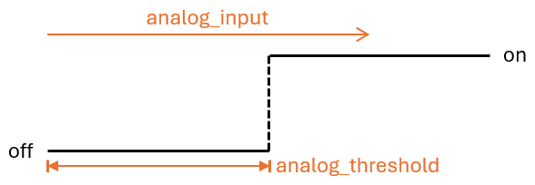
当将模拟信号视为“识别”(转盘的标记区域)并且将视为“未识别”(未识别的区域(未标记的转盘区域)时,阈值analog_threshold threshold控制。如果ADC传感器的值大于阈analog_input ,则将标记视为识别,较小或相同,则无法识别。
现在必须执行以下配置步骤,例如,软件方面:
 sensor :
  - platform : adc
    id : adc_input
    pin : GPIO17
    internal : true
    raw : true
    samples : 10
update_interval : 50ms number :
- platform : template
id : adc_threshold
name : ADC Schwellwert
icon : mdi:speedometer-slow
entity_category : config
mode : box
optimistic : true
initial_value : 50
min_value : 0
max_value : 1000
step : 1analog_input analog_threshold 2创建的数字组件。 ferraris :
id : ferraris_meter
analog_input : adc_input
analog_threshold : adc_threshold
# ...analog_threshold的固定数值。在这种情况下,可以省略步骤2。 ferraris :
# ...
analog_threshold : 45
# ...偏移值的配置off_tolerance和on_tolerance与配置analog_threshold非常相似,因此在上面的示例中未明确显示。
示例配置: ferraris_meter_analog.yaml
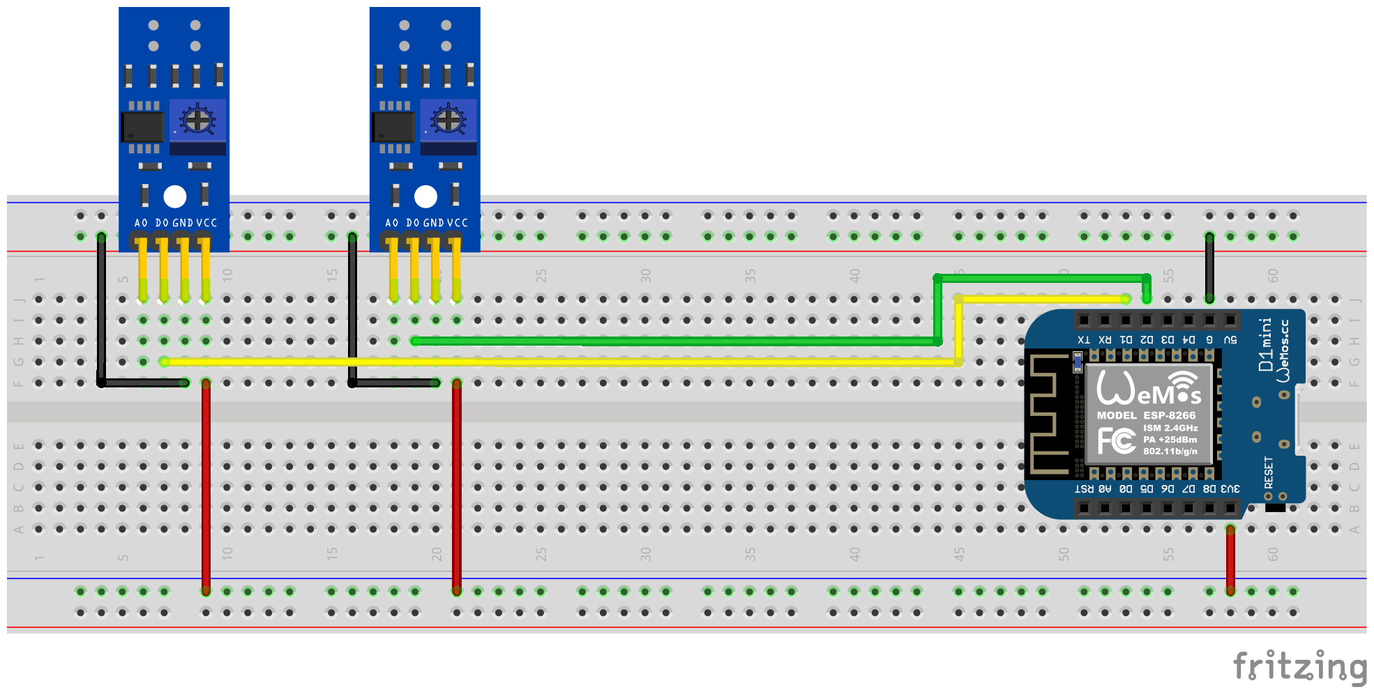
也可以使用单个ESP微控制器读取多个超过一个法拉利当前计数器。为此,您需要在微控制器上进行更多的红外传感器 / TCRT5000模块和其他免费的GPIO引脚。如前所述,TCRT5000模块通过VCC和GND连接到ESP微控制器的电压源,并且D0输出各自连接到ESP板,并使用免费的GPIO PIN连接到ESP板。
笔记
从理论上讲,变体也可以与红外传感器的模拟输出一起使用,但是ESP微控制器上具有ADC能力的引脚比纯数字引脚更有限。因此,特别是只有一个ADC的ESP8266不适合通过其模拟输出来支持多个红外传感器。
以下插件电路图显示了一个测试设置的示例,该测试设置具有连接到ESP8266 D1 mini的两个TCRT5,000模块。
但是,应该记住的是,每个其他红外传感器都会增加微控制器上的负载,尤其是在转盘非常高的速度下,硬件使其更接近其限制。
现在必须执行以下配置步骤,例如,软件方面:
 ferraris :
  - id : ferraris_meter_1
    digital_input : GPIO4
    # ...
  - id : ferraris_meter_2
    digital_input : GPIO5
# ...ferraris_id分配法拉利组件的相应实例。 sensor :
- platform : ferraris
ferraris_id : ferraris_meter_1
power_consumption :
name : Momentanverbrauch 1
energy_meter :
name : Verbrauchszähler 1
- platform : ferraris
ferraris_id : ferraris_meter_2
power_consumption :
name : Momentanverbrauch 2
energy_meter :
name : Verbrauchszähler 2
binary_sensor :
- platform : ferraris
ferraris_id : ferraris_meter_1
rotation_indicator :
name : Umdrehungsindikator 1
- platform : ferraris
ferraris_id : ferraris_meter_2
rotation_indicator :
name : Umdrehungsindikator 2
switch :
- platform : ferraris
ferraris_id : ferraris_meter_1
calibration_mode :
name : Kalibrierungsmodus 1
- platform : ferraris
ferraris_id : ferraris_meter_2
calibration_mode :
name : Kalibrierungsmodus 2示例配置: ferraris_meter_multi.yaml
在定位和对齐红外传感器以及电位计或模拟阈值值的调整期间,衡量素毛素电流计的转盘的转速并计算消耗并计算传感器条件的变化与转盘的实际检测相对应。因此,可以通过打开开关以进行校准模式(请参阅执行器),将法拉利组件放入校准模式。只要激活校准模式,就不会对消耗数据进行计算,也不会更改相应的传感器(请参见主传感器)。取而代之的是,用于旋转指示的诊断传感器(请参阅诊断传感器)是有效的,也可以用于支持正确的对齐。传感器处于on何时在转盘上识别出标记,并且如果未识别标记,则off 。
为了能够使用校准模式,必须在yaml文件中配置组件calibration_mode和rotation_indicator :
 binary_sensor :
  - platform : ferraris
    rotation_indicator :
      name : Umdrehungsindikator

switch :
  - platform : ferraris
    calibration_mode :
name : Kalibrierungsmodus从未标记到标记区域的过渡,反之亦然,转盘上可以导致传感器的识别状态的快速来回(“弹跳”),尤其是在慢速旋转速度下发生,并且不能被校准完全抑制。这种瘀伤导致伪造的测量结果并避免使用以下设置。
debounce_threshold凹陷阈值指定跌落和随后的侧面增加之间的最短时间。只有当测量的时间位于配置值上方的两个侧面之间,传感器就考虑到了传感器。当使用数字和模拟输入信号的红外传感器时,这种类型的抑郁症可以工作。
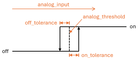
可以将两个偏移值off_tolerance和on_tolerance配置为使用磁滞特征,以通过模拟信号检测转盘上标记的区域。这补偿了模拟信号的“颤抖”,从而最大程度地减少了转盘上标记区域的识别状态的可能性。这种类型的抑郁仅在使用红外传感器的模拟输入信号时起作用。
通过对更新间隔update_interval的巧妙配置以及模拟传感器analog_input的每次更新的采样数( samples ),模拟信号的曲线可以平滑,以至于消除了短期波动。但是,应该记住的是,太大的更新间隔可能会导致以下事实:个人旋转不再以很高的转动速度认识到,因为增加和随后的侧面侧面之间的时间小于设定的更新间隔。这种类型的抑郁症也只有在使用红外传感器的模拟输入信号时起作用。
为了用法拉利电流仪表的实际仪表来补偿法拉利组件中的仪表状态,可以明确覆盖消耗仪传感器的值。为此,两个ferraris.set_energy_meter和ferraris.set_rotation_counter 。
提示
通常,这两个动作中只有一项需要,具体取决于您要在千瓦时或旋转数量中将仪表放置。
根据用户界面或自动脚本自动处理仪表级别的设置,可以以不同的方式使用操作。下面描述了两个可能的申请示例,但此处没有其他选项。
例如,为此,进行了以下配置步骤(在此示例中,将仪表支架设置为千瓦小时值):
 number :
  - platform : template
    id : target_energy_value
    name : Manueller Zählerstand
    icon : mdi:counter
    unit_of_measurement : kWh
    device_class : energy
    entity_category : config
    mode : box
    optimistic : true
    min_value : 0
    max_value : 1000000
step : 0.01 button :
- platform : template
name : Verbrauchszähler überschreiben
icon : mdi:download
entity_category : config
on_press :
- ferraris.set_energy_meter :
id : ferraris_meter
value : !lambda |-
float val = id(target_energy_value).state;
return (val >= 0) ? val : 0; 例如,为此,执行了以下配置步骤:
ferraris.set_energy_meter活动)。 api :
# ...
actions :
- action : set_energy_meter
variables :
target_value : float
then :
- ferraris.set_energy_meter :
id : ferraris_meter
value : !lambda |-
return (target_value >= 0)
? target_value
: 0;- id : ' 1234567890 '
alias : Zurücksetzen des Verbrauchszählers
trigger :
- platform : time
at : 00:00:00
condition :
- condition : template
value_template : ' {{ now().day == 1 }} '
action :
- action : esphome.ferraris_meter_set_energy_meter
data :
target_value : 0
mode : single为了不缩短ESP微控制器上闪存的寿命,Ferraris组件不会在闪存中持续保存任何数据。结果,它不能首先记住在微控制器的重新启动下的仪表状态,并且计数器开始在每条船上以0 kWh的速度计数。因此,在每次重新启动后,您必须通过在法拉利电流仪表上读取的值手动覆盖仪表。由于这不是很友好的用户,因此有可能在家庭助理中持续下一个仪表状态,并在启动微控制器时将其传输到它。
为了使此功能工作,必须执行以下配置步骤,例如:
input_number.stromzaehler_letzter_wert )。 number :
- platform : homeassistant
id : last_energy_value
entity_id : input_number.stromzaehler_letzter_wertenergy_start_value是指2下的数字组件。 ferraris :
# ...
energy_start_value : last_energy_value- id : ' 1234567890 '
alias : Aktualisierung Verbrauchszähler-Cache
trigger :
- platform : state
entity_id :
- sensor.ferraris_meter_verbrauchszaehler
condition : []
action :
- action : input_number.set_value
target :
entity_id : input_number.stromzaehler_letzter_wert
data :
value : ' {{ states(trigger.entity_id) }} '
mode : singleenergy_meter的传感器自动化,从而更新2下的数字组件。但是,这扩展了微控制器中每次革命的处理时间,并且可以导致转盘的单个回合的事实,即在非常高的电力消耗的情况下不会记录转盘的单个回合。因此,我建议使用家庭助理自动化的变体。Ferraris仪表是一种用于创建ESP固件的大量组件,该组件使用ESP微控制器和红外传感器旋转次数以及模拟法拉利电气表的体操次数以及计算当前的电力消耗和仪表读数。然后可以将论文值发送到家庭自动化软件搜索作为家庭助理以进行进一步处理。
该软件(包括带有示例硬件设置的文档)是“原样”提供的,没有任何形式,明示或暗示的保修,包括但不限于商品的保证,特定目的的适用性和非侵权。在任何情况下,无论是在合同,侵权还是其他责任中,作者或版权持有人都不应对任何索赔,损害赔偿或其他责任,无论是由合同,侵权还是其他责任。
在硬件方面,要求仅使用ESP微控制器(例如ESP8266或ESP32,包括电源)和红外传感器(例如TCRT5000)。 ESP8266微控制器完全足以满足法拉利仪表的纯粹功能。对于红外传感器,有可用的3.3V-5V输入电压基于现成的TCRT5000突破模块,因此具有可调节电阻(电位计)来校准传感器的数字输出。论文TCRT5000模块具有4个引脚-VCC和GND,用于传感器芯片的电源以及数字输出D0和模拟输出A0。
将传感器放在法拉利电量表的盖板上需要一些技巧和精确工作。传感器的红外发射器/接收器对必须以毫米精度将转盘的中央对齐,并在直线上以直线与转盘处对齐。
Ferraris仪表组件基本上支持以下设置变体:
要构建一个大声的固件,您必须生物基于YAML的配置文件。您可以使用该存储库中证明的示例配置文件之一作为起点,并根据您的需求进行调整。
原则上,有两种构建Esphome固件的方法:
您应该选择哪种方法取决于您对Esphome的熟悉程度,以及您是否喜欢使用图形用户界面或命令行。此外,您正在构建的主机的性能可以在加速过程中发挥作用。
笔记
没有必要分配此存储库,并对示例配置进行改编,直接在分叉存储库中。取而代之的是,将示例配置保存并在本地保存并将其存储在家庭助理主机上是足够的(如果您希望使用Esphome设备编译器附加组件构建Esphome固件)。
以下各节描述了固件配置文件中最著名的组件。
法拉利组件是必不可少的,必须添加才能使用其传感器。
由于这是一个自定义组件,它不是Esphome的一部分,因此必须明确导入它。最简单的方法是直接从此存储库中加载组件。
 external_components :
  - source : github://jensrossbach/esphome-ferraris-meter
    components : [ferraris]
提示
在上面的示例中,加载了来自存储库main分支的组件的最新版本。但是,我建议使用版本编号参考发布的版本,以便对使用哪种软件版本进行更多控制,并能够对“破坏更改”做出更好的反应。有关如何完成此操作,请参见示例配置。
可以配置以下通用配置项目:
| 选项 | 类型 | 必需的 | 默认 | 描述 |
|---|---|---|---|---|
id | ID | 否1 | - | 法拉利组件实例 |
digital_input | 别针 | 是2 | - | TCRT5000模块的数字输出连接到的GPIO PIN |
analog_input | ID | 是2 | - | ADC传感器读取连接到TCRT5000模块的模拟输出的引脚 |
analog_threshold | 号码 / ID 3 | 不 | 50 | 通过模拟输入检测旋转的阈值值 |
off_tolerance | 号码 / ID 3 | 不 | 0 | 落下边缘的模拟阈值负偏移,请参见部分辩论详细信息 |
on_tolerance | 号码 / ID 3 | 不 | 0 | 对上升边缘的模拟阈值的积极偏移,请参见详细信息请参见部分 |
rotations_per_kwh | 数字 | 不 | 75 | 通过KWH的转盘的旋转数量(通常在法拉利电表上注意到该值) |
debounce_threshold | 号码 / ID 3 | 不 | 400 | 毫秒下降的最短时间跌落,随后的上升边缘要考虑旋转,请参见详细信息,请参阅部分。 |
energy_start_value | ID | 不 | - | 启动时间将其值用作能量计数器的起始值的数字组件 |
1一些用例需要配置元素id 。
2只有digital_input或analog_input之一是请求,具体取决于硬件设置变体。
3配置元素analog_threshold , off_tolerance , on_tolerance和debounce_threshold期望静态编号或数字组件上的ID。后者允许通过用户界面(例如,使用模板号)配置该值。
 ferraris :
  id : ferraris_meter
  digital_input : GPIO4
  rotations_per_kwh : 75
  debounce_threshold : 400
energy_start_value : last_energy_value如果将ESP集成到家庭助理中,则需要对API组件。对于应使用替代家庭自动化软件的情况,必须添加MQTT组件。但是,某些机制在手动覆盖能量表或恢复重新启动后(以下湖面以获取细节)后搜索最后的读数可能不再起作用。
请参见下文示例,将集成到家庭助理(与加密API)中:
 api :
  encryption :
    key : !secret ha_api_key
下面是通过MQTT使用替代家庭自动化软件使用的示例:
 mqtt :
  broker : 10.0.0.2
  username : !secret mqtt_user
password : !secret mqtt_passwordWiFi组件应存在,因为否则,传感器值不能轻易传输到另一台计算机。
 wifi :
  ssid : !secret wifi_ssid
password : !secret wifi_password法拉利组件提供了主要传感器,以揭示计算出的消耗量值以及校准模式的诊断传感器。所有传感器都是可选的,如果不需要,可以省略。
可以配置以下主要传感器:
| 传感器 | 类型 | 设备类 | 州类 | 单元 | 描述 |
|---|---|---|---|---|---|
power_consumption | 数字 | power | measurement | w | 当前的功耗 |
energy_meter | 数字 | energy | total_increasing | WH | 总能耗(仪表读数) |
有关每个项目的详细配置选项,请参阅Esphome传感器组件配置。
 sensor :
  - platform : ferraris
    power_consumption :
      name : Power consumption
    energy_meter :
name : Meter reading 可以配置以下诊断传感器:
| 传感器 | 类型 | 描述 |
|---|---|---|
rotation_indicator | 二进制 | 指示转盘上的标记是否在红外传感器的前面(仅在校准模式下起作用) |
有关每个项目的详细配置选项,请参阅Esphome二进制传感器组件配置。
 binary_sensor :
  - platform : ferraris
    rotation_indicator :
name : Rotation indicator为了诊断目的,法拉利组件提供了一个名称calibration_mode的开关。它可用于将组件设置为校准时尚(有关更多信息,请参见部分校准)。
 switch :
  - platform : ferraris
    calibration_mode :
name : Calibration mode法拉利组件提供了两个动作,用于设置能级读数和旋转计数器。
| 行动 | 描述 |
|---|---|
ferraris.set_energy_meter | 将能量表读数设置为提供的值 |
| 范围 | 类型 | 范围 | 描述 |
|---|---|---|---|
value | float | > = 0 | 千瓦时能量表读数的目标值(kWh) |
笔记
尽管当前仪表读数的传感器具有单位WH(瓦小时) ,但越过仪表读数的动作具有单位kWh(千瓦时) ,因为模拟法拉利素电表通常通常在本单元中显示仪表读数。
| 行动 | 描述 |
|---|---|
ferraris.set_rotation_counter | 将旋转计数器设置为提供的值 |
笔记
在内部旋转时,旋转柜台的旋转柜台间接地设置了能量计读数的动作,而不是与瓦特小时或千瓦小时一起使用。
| 范围 | 类型 | 范围 | 描述 |
|---|---|---|---|
value | uint64 | > = 0 | 旋转数量旋转计数器数量的目标值 |
本节描述了法拉利组件使用的各种示例。
在此变体中,红外传感器的数字输出用于检测转盘的旋转。不需要模拟输出,其他引脚必须连接到微控制器的相应引脚。 ESP的3.3V输出应用于VCC,并且必须将数字输出D0连接到免费的GPIO引脚(例如GPIO4,对应于D1 Mini上的PIN D2)。
以下面包板示意图显示了使用ESP8266 D1 Mini开发板作为微控制器的示例测试设置。
红外传感器的数字输出信号必须通过电报机使用船尾校准;传感器背面的两个绿色LED对此有所帮助。当传感器提供功率时,右手LED会连续亮起。只要未检测到“障碍”并在反射中断时,左手LED灯光就会升高。后者是当传感器前方的Ferraris电力计的转盘移动时的状态。因此,电位计SHEDT的调节甜菜因此,使左手LED在标记不在红外发射器/接收器对范围内时亮起来,并且随着标记在其前方移动时就会熄灭。这只是一个很小的范围,很难找到此设置。 To Further Assist with this Process, the Calibration Mode Can Be Enabled In The Ferraris Meter Firmware, See Section Calibration for Details.
提示
In case you are unable to find an appropriate and working adjustment of the potentiometer, you can alternatively use the analog output of the infrared sensor, see next section.
On the software side, the pin which is connected to the digital output of the TCRT5000 module has to be configured for the Ferraris component in the YAML configuration file:
 ferraris :
  id : ferraris_meter
  digital_input : GPIO4
  # ...
Example configuration file: ferraris_meter_digital.yaml
In this variant, the analog output of the infrared sensor is used to detect rotations of the turntable. The digital output is not required, the other pins must be connected to the corresponding pins of the microcontroller. The 3.3V output of the ESP should be used for VCC and the analog output A0 must be connected to a free ADC pin (eg GPIO17, corresponding to pin A0 on the D1 Mini).
The following breadboard schematic shows an example test setup using an ESP8266 D1 Mini development board as microcontroller.
A calibration using the potentiometer on the TCRT5000 module is not needed. Instead, the threshold for the analog input and optionally the offset values for a hysteresis curve must be configured on the software side (see also section Debouncing further down). Here as well, the calibration mode of the Ferraris component could be helpful, see section calibration for details.
The threshold value analog_threshold controls when the analog signal is treated as "detected" (marked area of the turntable) and when it is treated as "not detected" (unmarked area of the turntable). If the value from the ADC sensor analog_input is greater than the threshold value, the marking is considered detected; if it is smaller than or equal to the threshold value, it is considered not detected.
On the software side, for instance, the following configuration steps must now be carried out:
 sensor :
  - platform : adc
    id : adc_input
    pin : GPIO17
    internal : true
    raw : true
    samples : 10
update_interval : 50ms number :
- platform : template
id : adc_threshold
name : ADC threshold
icon : mdi:speedometer-slow
entity_category : config
mode : box
optimistic : true
initial_value : 50
min_value : 0
max_value : 1000
step : 1analog_input refers to the ADC sensor created under 1. and the entry analog_threshold refers to the number component created under 2. ferraris :
id : ferraris_meter
analog_input : adc_input
analog_threshold : adc_threshold
# ...analog_threshold if the threshold value is already known and no longer needs to be configured/changed. In this case, step 2 can be omitted. ferraris :
# ...
analog_threshold : 45
# ... The configuration for the offset values off_tolerance and on_tolerance is very similar to the configuration of analog_threshold and therefore not explicitly shown in above example.
Example configuration file: ferraris_meter_analog.yaml
It is also possible to read more than one Ferraris electricity meter with a single ESP microcontroller. This requires multiple infrared sensors / TCRT5000 modules and additional free GPIO pins on the microcontroller. The TCRT5000 modules have to be connected to the voltage source of the ESP microcontroller via VCC and GND as described in the section Hardware Setup and the D0 outputs have to be connected to free GPIO pins on the ESP board.
笔记
Theoretically, the variant with the analog output of the infrared sensor can also be used, but the ADC-capable pins on the ESP microcontrollers are stronger limited than the pure digital pins. Especially the ESP8266, which has a single ADC only, would therefore not be suitable to support multiple infrared sensors via their analog outputs.
The following breadboard schematic shows an example of an example test setup with two TCRT5000 modules connected to an ESP8266 D1 Mini.
However, bear in mind that each additional infrared sensor increases the load on the microcontroller and brings the hardware closer to its limits, especially with very high rotation speeds of the turntables.
On the software side, for instance, the following configuration steps must now be carried out:
 ferraris :
  - id : ferraris_meter_1
    digital_input : GPIO4
    # ...
  - id : ferraris_meter_2
    digital_input : GPIO5
# ...ferraris_id configuration entry. sensor :
- platform : ferraris
ferraris_id : ferraris_meter_1
power_consumption :
name : Power consumption 1
energy_meter :
name : Meter reading 1
- platform : ferraris
ferraris_id : ferraris_meter_2
power_consumption :
name : Power consumption 2
energy_meter :
name : Meter reading 2
binary_sensor :
- platform : ferraris
ferraris_id : ferraris_meter_1
rotation_indicator :
name : Rotation indicator 1
- platform : ferraris
ferraris_id : ferraris_meter_2
rotation_indicator :
name : Rotation indicator 2
switch :
- platform : ferraris
ferraris_id : ferraris_meter_1
calibration_mode :
name : Calibration mode 1
- platform : ferraris
ferraris_id : ferraris_meter_2
calibration_mode :
name : Calibration mode 2Example configuration file: ferraris_meter_multi.yaml
During the positioning and alignment of the infrared sensor as well as the adjustment of the potentiometer or the analog threshold, it makes little sense to measure the rotations of the Ferraris electricity meter's turntable and calculate the consumption values, as the changes in state of the sensor do not correspond to the actual detection of the mark on the turntable. It is therefore possible to set the Ferraris component to calibration mode by turning on the calibration mode switch (see Actors). As long as the calibration mode is activated, no calculation of the consumption data is performed and the corresponding sensors (see Primary Sensors) are not changed. Instead, the diagnostic sensor for the rotation indication (see Diagnostic Sensors) is active and can additionally be used to assist with correct alignment. The sensor has the on state when the marker on the turntable is detected and the off state when it is not detected.
To be able to use the calibration mode, the components calibration_mode and rotation_indicator must be configured in the YAML file:
 binary_sensor :
  - platform : ferraris
    rotation_indicator :
      name : Rotation indicator

switch :
  - platform : ferraris
    calibration_mode :
name : Calibration modeThe transition from unmarked to marked area and vice versa on the turntable can lead to a rapid back and forth jump ("bouncing") in the detection state of the sensor, which occurs particularly at slow rotation speeds and cannot be completely suppressed by the calibration. This bouncing of the state leads to falsified measured values and to avoid this, the following settings can be applied.
The debounce threshold value debounce_threshold specifies the minimum time in milliseconds between falling and subsequent rising edge. The trigger from the sensor is only taken into account if the measured time between the two edges is above the configured value. This type of debouncing can be applied to both the variant using the digital as well as the analog input signal of the infrared sensor.
The two offset values off_tolerance and on_tolerance can be configured to use a hysteresis curve for the detection of the marked area on the turntable via the analog signal. This compensates the jitter of the analog signal and thus minimizes any possible bouncing of the detection status for the marked area on the turntable. This type of debouncing only works when using the analog input signal of the infrared sensor.
By carefully configuring the update interval update_interval and the number of samples per update ( samples ) for the analog sensor analog_input , the curve of the analog signal can be smoothed to such an extent that short-term fluctuations are eliminated. However, bear in mind that excessive update intervals can lead to individual rotations no longer being detected at very high rotation speeds, as the time between the rising and subsequent falling edge is then shorter than the set update interval. Also this type of debouncing only works when using the analog input signal of the infrared sensor.
To synchronize the meter reading in the Ferraris component with the actual meter reading of the Ferraris electricity meter, the value of the energy meter sensor can be explicitly overwritten. The two actions ferraris.set_energy_meter and ferraris.set_rotation_counter (see Actions) are provided for this purpose.
提示
Usually, you need to use only one of the two actions, depending on whether you want to set the meter reading in kilowatt hours or in number of rotations.
The actions can be used in different ways, depending on whether the energy meter reading is to be set manually via the user interface or trigger-based via automations and scripts. Two possible usage examples are described below, but there are more possibilities existing which are not described here.
For instance, the following configuration steps are carried out (in this example to overwrite the energy meter with a kilowatt hours value):
 number :
  - platform : template
    id : target_energy_value
    name : Manual meter reading
    icon : mdi:counter
    unit_of_measurement : kWh
    device_class : energy
    entity_category : config
    mode : box
    optimistic : true
    min_value : 0
    max_value : 1000000
step : 0.01 button :
- platform : template
name : Overwrite meter reading
icon : mdi:download
entity_category : config
on_press :
- ferraris.set_energy_meter :
id : ferraris_meter
value : !lambda |-
float val = id(target_energy_value).state;
return (val >= 0) ? val : 0; For instance, the following configuration steps are carried out:
ferraris.set_energy_meter is used). api :
# ...
actions :
- action : set_energy_meter
variables :
target_value : float
then :
- ferraris.set_energy_meter :
id : ferraris_meter
value : !lambda |-
return (target_value >= 0)
? target_value
: 0;- id : ' 1234567890 '
alias : Reset energy meter reading
trigger :
- platform : time
at : 00:00:00
condition :
- condition : template
value_template : ' {{ now().day == 1 }} '
action :
- action : esphome.ferraris_meter_set_energy_meter
data :
target_value : 0
mode : singleIn order not to reduce the service life of the flash memory on the ESP microcontroller, the Ferraris component does not store any data persistently in the flash. As a result, it cannot remember the meter reading after a restart of the microcontroller and the meter starts counting at 0 kWh with every boot process. Therefore, the meter reading would have to be overwritten manually with a value read from the Ferraris electricity meter after each restart. As this is not very user-friendly, there is the option of persisting the last meter reading in Home Assistant and transferring it to the microcontroller when booting.
For this to work, the following configuration steps must be carried out:
input_number.electricity_meter_last_value ). number :
- platform : homeassistant
id : last_energy_value
entity_id : input_number.electricity_meter_last_valueenergy_start_value refers to the number component created under 2. ferraris :
# ...
energy_start_value : last_energy_value- id : ' 1234567890 '
alias : Update meter reading cache
trigger :
- platform : state
entity_id :
- sensor.ferraris_meter_energy
condition : []
action :
- action : input_number.set_value
target :
entity_id : input_number.electricity_meter_last_value
data :
value : ' {{ states(trigger.entity_id) }} '
mode : singleenergy_meter in the YAML configuration file which updates the number component created under 2 directly from ESPHome. However, this leads to a longer processing time per rotation in the microcontroller and may result in individual rotations of the turntable not being detected in the event of very high power consumption (and hence, very high rotation speeds). Therefore, I recommend the variant with the automation in Home Assistant.

