esphome ferraris meter
Release 1.4.1
note
This is the German version, for the English version, scroll down or click here.
Ferraris meter is an ESPHOME component for creating ESP firmware, which can use an ESP microcontroller and infrared sensor to determine the speed and revolutions of the turntable of an analog ferraris stream meter and from this can calculate the current electricity consumption and the meter state. These values can then be sent to home automation software such as Home Assistant for further processing.
The software (including the documentation with hardware sample structures) is provided without defaulting and without any express or tacit warranty, including, but not limited to guaranteeing market access, the suitability for a specific purpose and the non-infringement of third party rights. The authors or copyright owners are in no way liable for claims, damage or other obligations, whether in a contract or liability lawsuit, an unauthorized act or otherwise, which arise from or in connection with the software or use or other shops with the software.
Only an ESP microcontroller (e.g. ESP8266 or ESP32, including voltage supply) and an infrared sensor (e.g. TCRT5000) are required. For the pure functionality of the Ferraris meter, an ESP8266 is completely sufficient as a microcontroller. For the infrared sensor, there are finished TCRT5000-based breakout modules with 3.3V-5V input voltage, which also have a controllable resistance (potentiometer) to calibrate the digital output. These TCRT5000 modules have 4 pins-VCC and GND for the power supply of the sensor chip as well as a digital output D0 and an analog output A0.
When placing the sensor on the cover plate of the Ferraris current meter, a little skill and precision work is required. The infrared transmitter/recipient couple of the sensor must be aligned in the middle of the millimeter precise over the turntable and pointed straight on the turntable.
In principle, the Ferraris meter component supports the following development variants:
To create ESPHOME firmware, a Yaml-based configuration file must be created. You can use one of the sample configuration files provided in this repository as a starting point and adapt them to your needs.
In principle, there are two ways to build the Esphome firmware:
Which method you should choose depends on how trust you are with Esphome and whether you prefer to work with a graphical user interface or with the command line. In addition, the performance of the host on which you build the firmware could play a role to accelerate the process.
note
It is not necessary to copy this repository ("forken") and to adapt to the sample configuration in the copied repository. Instead, it is sufficient to save and adapt the sample configuration or take off the adapted configuration on your home assistant host (should the creation of the ESPHOME firmware be desired using the Esphome Device Compiler add-on).
The following sections describe the most important components included in the firmware configuration file.
The component Ferraris is essential and must be added to use your sensors.
Since it is a custom component that is not part of ESPHOME, it must be explicitly imported. The easiest way is to load the component directly from this repository.
 external_components :
  - source : github://jensrossbach/esphome-ferraris-meter
    components : [ferraris]
Tip
In the example above, the latest status of the component is invited from the main branch of the repositorie. However, I recommend referring to a released stand by means of a version number to have more control over which software stand is used and in order to be able to react better to "Breaking Changes". See sample configuration how this can be done.
The following generic settings can be configured:
| option | type | Needed | standard | Description |
|---|---|---|---|---|
id | ID | No 1 | - | Instance of the Ferraris component |
digital_input | Pin | yes 2 | - | GPIO PIN with which the digital output of the TCRT5000 module is connected |
analog_input | ID | yes 2 | - | ADC sensor that reads the PIN connected to the analog output of the TCRT5000 module |
analog_threshold | Number / ID 3 | no | 50 | Threshold for the detection of a revolution via the analog input |
off_tolerance | Number / ID 3 | no | 0 | Negative offset on the analog threshold value for the falling flank, see section Depressing for details |
on_tolerance | Number / ID 3 | no | 0 | Positive offset on the analog threshold value for the rising flank, see section depressing for details |
rotations_per_kwh | Number | no | 75 | Number of revolutions of the turntable per kWh (the value is noted on the Ferraris current meter) |
debounce_threshold | Number / ID 3 | no | 400 | Minimal time in milliseconds between falling and subsequent increasing flank so that the revolution is taken into account, see section Deprolling for Details |
energy_start_value | ID | no | - | Number components whose value is used in booting as a start value for the consumption meter |
1 Certain applications require the configuration element id .
2 only one of the two configuration elements - digital_input or analog_input - is required, depending on the hardware development variant.
3 The configuration elements analog_threshold , off_tolerance , on_tolerance and debounce_threshold Either expect a fixed number or the ID of a number component. The latter enables the value to be configured via the user interface (e.g. by using a template number component).
 ferraris :
  id : ferraris_meter
  digital_input : GPIO4
  rotations_per_kwh : 75
  debounce_threshold : 400
energy_start_value : last_energy_valueAn API component is required if the ESP is to be integrated into Home Assistant. In the event that an alternative home automation software is to be used, a MQTT component must be added instead. However, certain mechanisms such as overwriting the meter stand or the restoration of the last meter scale after a restart (see below for details) and no longer work.
Below is an example of integration with Home Assistant (and encrypted API):
 api :
  encryption :
    key : !secret ha_api_key
And here is an example of use with an alternative home automation software using MQTT:
 mqtt :
  broker : 10.0.0.2
  username : !secret mqtt_user
password : !secret mqtt_passwordA WiFi component should be available, otherwise the sensor values cannot be easily transferred to another device.
 wifi :
  ssid : !secret wifi_ssid
password : !secret wifi_passwordThe Ferraris component has primary sensors to output the calculated consumption values and diagnostic sensors for calibration mode. All sensors are optional and can be left out if they are not needed.
The following primary sensors can be configured:
| sensor | type | Device class | State class | Unit | Description |
|---|---|---|---|---|---|
power_consumption | numerical | power | measurement | W | Current power consumption |
energy_meter | numerical | energy | total_increasing | WH | Total current consumption (electricity meter/meter state) |
You can find detailed information on the configuration options of the individual elements in the documentation of the ESPHOME sensor components.
 sensor :
  - platform : ferraris
    power_consumption :
      name : Momentanverbrauch
    energy_meter :
name : Verbrauchszähler The following diagnostic sensors can be configured:
| sensor | type | Description |
|---|---|---|
rotation_indicator | binary | Shows whether the marking on the turntable is just in front of the infrared sensor (only works in calibration mode) |
You can find detailed information on the configuration options of the individual elements in the documentation of the Esphome binary sensor components.
 binary_sensor :
  - platform : ferraris
    rotation_indicator :
name : Umdrehungsindikator For diagnostic purposes, the Ferraris component has a switch. This has the name calibration_mode and can be used to put the component into the calibration mode (see section Calibration for more information).
 switch :
  - platform : ferraris
    calibration_mode :
name : KalibrierungsmodusThe Ferraris component provides two actions for setting the meter scale and setting the transition counter.
| action | Description |
|---|---|
ferraris.set_energy_meter | Places the meter state on the specified value |
| parameter | type | Area | Description |
|---|---|---|---|
value | float | > = 0 | Target value for the meter state in kilowatt hours (kWh) |
note
Although the sensor for the current meter state has the unit WH (watt hours) , the action to overwrite the meter stand uses the unit kWh (kilowatt hours) , since the analog ferraris current meter usually also display the meter.
| action | Description |
|---|---|
ferraris.set_rotation_counter | Places the revolving counter on the specified value |
note
The action for setting the meter stand indirectly also sets the revolving counter, since the Ferraris component works internally with revolutions and not with watt hours or kilowatt hours.
| parameter | type | Area | Description |
|---|---|---|---|
value | uint64 | > = 0 | Target value for the turnover counter in number revolutions |
Various application examples for the Ferraris component are described in this section.
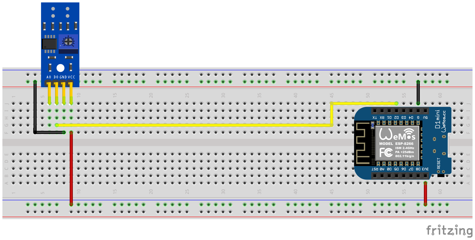
In this variant, the digital output of the infrared sensor is used to identify revolutions of the turntable. The analog output is not required, the other pins must be connected to the corresponding pins of the microcontroller. For VCC, the 3.3V output of the ESPS should be used and the digital output D0 must be connected to a free GPIO PIN (e.g. GPIO4, corresponds to the PIN D2 on the D1 mini).
The following plug-in circuit diagram shows an example of an experimental setup with an ESP8266 D1 Mini Development Board as a microcontroller.
With the help of a screwdriver, the digital output signal must then be calibrated via the potentiometer. The two green LEDs on the back of the sensor help. The right LED shines permanently when the sensor is supplied with electricity. The left LED shines as long as no "obstacle" has been recognized and expires when the reflection has been interrupted. The latter is the condition when the marking on the turntable of the Ferraris current meter wanders in front of the sensor. The potentiometer should therefore be set so that the left LED still shines when the marking is not in the area of the Infrared Sender/Recipient couple as soon as the marker pushes in front of it. This is only a very small area and it can be a little difficult to find this setting. For additional support for this process, the calibration mode can be activated in the Ferraris meter firmware, see section of calibration for details.
Tip
If it is not possible to find a suitable and functioning setting for the potentiometer, the analog output of the infrared sensor can alternatively be used, see next section.
Software side must be configured for the Ferraris component in the PIN YAML configuration file, which is connected to the digital output of the TCRT5000 module:
 ferraris :
  id : ferraris_meter
  digital_input : GPIO4
  # ...
Example configuration: ferraris_meter_digital.yaml
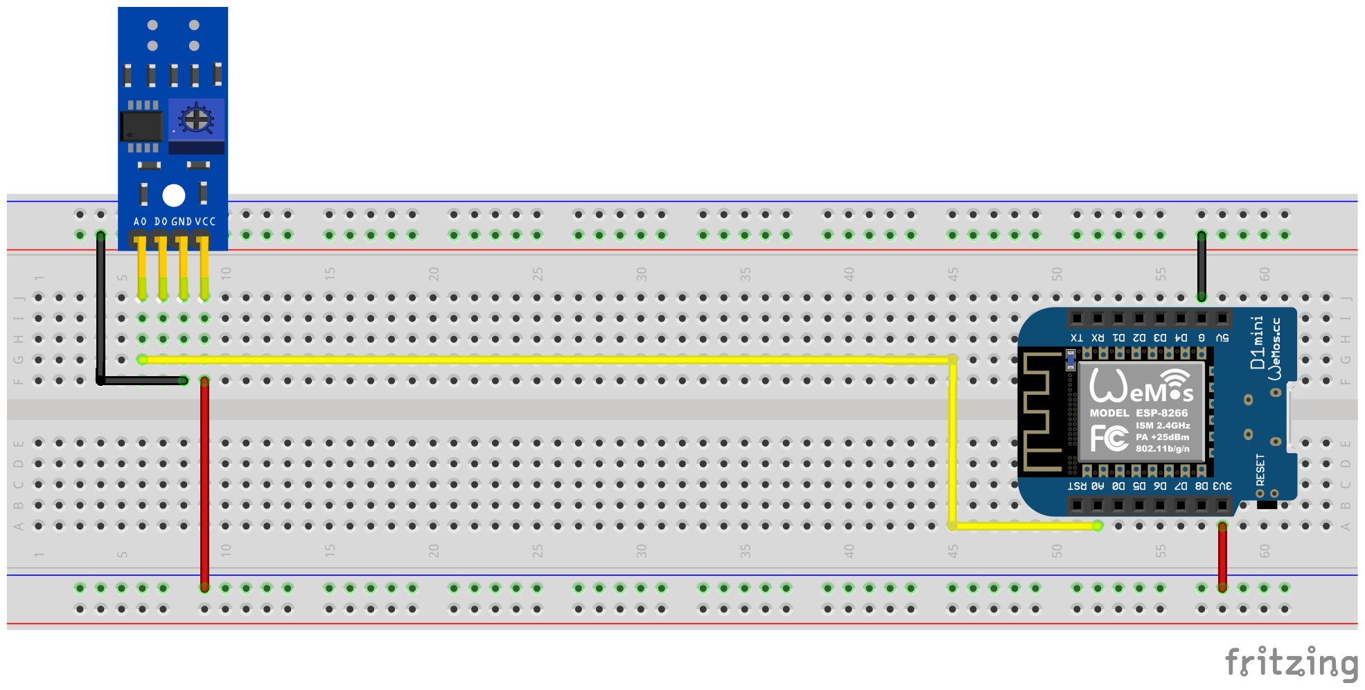
In this variant, the analog output of the infrared sensor is used to identify revolutions of the turntable. The digital output is not required, the other pins must be connected to the corresponding pins of the microcontroller. For VCC, the 3.3V output of the ESPS should be used and the analog output A0 must be connected to a free ADC pin (e.g. GPIO17, corresponds to the PIN A0 on the D1 mini).
The following plug-in circuit diagram shows an example of an experimental setup with an ESP8266 D1 Mini Development Board as a microcontroller.
Calibration by means of the potentiometer on the TCRT5000 module is no longer necessary, instead the software side must be configured for the analog input and optionally the offset values for a hysteresis characteristic (see also section depressing below). Here, too, the calibration mode of the Ferraris component can help, see section of calibration for details.
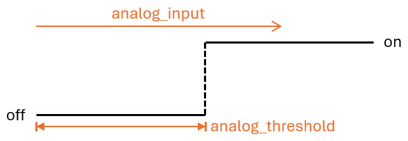
The threshold analog_threshold controls when the analogue signal is treated as "recognized" (marked area of the turntable) and when treated as "not recognized" (not marked area of the turntable). If the value of the ADC sensor is larger than the threshold analog_input , the marking is considered recognized, it is smaller or the same, it is not recognized.
The following configuration steps must now be carried out, for example, the software side:
 sensor :
  - platform : adc
    id : adc_input
    pin : GPIO17
    internal : true
    raw : true
    samples : 10
update_interval : 50ms number :
- platform : template
id : adc_threshold
name : ADC Schwellwert
icon : mdi:speedometer-slow
entity_category : config
mode : box
optimistic : true
initial_value : 50
min_value : 0
max_value : 1000
step : 1analog_input analog_threshold the number component created under 2. ferraris :
id : ferraris_meter
analog_input : adc_input
analog_threshold : adc_threshold
# ...analog_threshold can also be specified if the threshold is already known and no longer has to be configured/changed. In this case, step 2 can be omitted. ferraris :
# ...
analog_threshold : 45
# ... The configuration of the offset values off_tolerance and on_tolerance is very similar to configuring analog_threshold and was therefore not explicitly shown in the example above.
Example configuration: ferraris_meter_analog.yaml
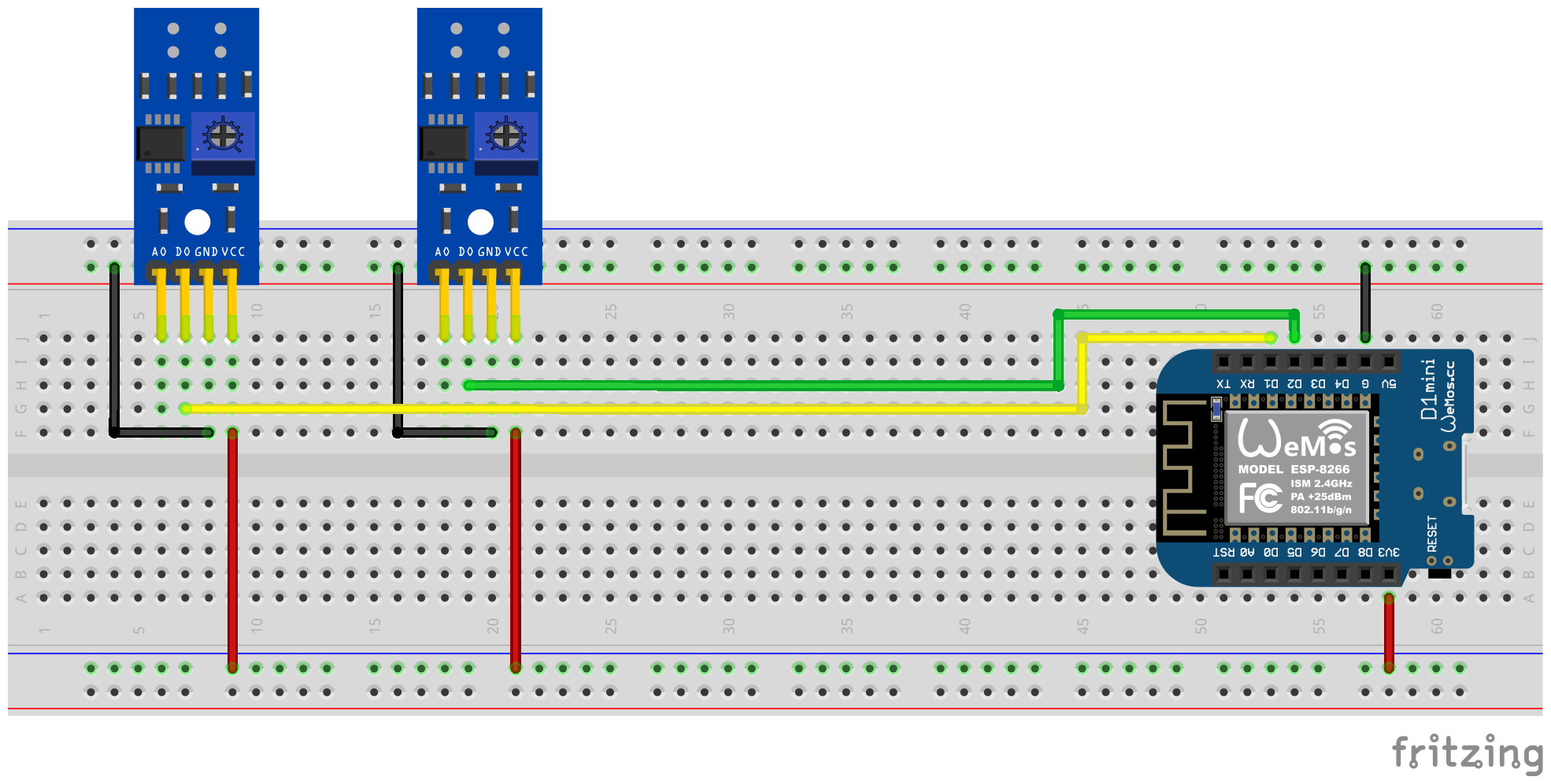
It is also possible to read more than one Ferraris current counter with a single ESP microcontroller. To do this, you need further infrared sensors / TCRT5000 modules and additional free GPIO pins on the microcontroller. As already described, the TCRT5000 modules are connected to the voltage source of the ESP microcontroller via VCC and GND and the D0 outputs are each connected to the ESP board with a free GPIO pin.
note
In theory, the variant can also be used with the analog output of the infrared sensor, but the ADC-capable pins on the ESP microcontrollers are more limited than the purely digital pins. In particular, the ESP8266, which only has one ADC, would therefore be unsuitable to support several infrared sensors through their analogue outputs.
The following plug-in circuit diagram shows an example of a test setup with two TCRT5,000 modules connected to an ESP8266 D1 mini.
However, it should be borne in mind that each additional infrared sensor increases the load on the microcontroller and, especially at very high speeds of the turntables, the hardware puts closer to its limits.
The following configuration steps must now be carried out, for example, the software side:
 ferraris :
  - id : ferraris_meter_1
    digital_input : GPIO4
    # ...
  - id : ferraris_meter_2
    digital_input : GPIO5
# ...ferraris_id . sensor :
- platform : ferraris
ferraris_id : ferraris_meter_1
power_consumption :
name : Momentanverbrauch 1
energy_meter :
name : Verbrauchszähler 1
- platform : ferraris
ferraris_id : ferraris_meter_2
power_consumption :
name : Momentanverbrauch 2
energy_meter :
name : Verbrauchszähler 2
binary_sensor :
- platform : ferraris
ferraris_id : ferraris_meter_1
rotation_indicator :
name : Umdrehungsindikator 1
- platform : ferraris
ferraris_id : ferraris_meter_2
rotation_indicator :
name : Umdrehungsindikator 2
switch :
- platform : ferraris
ferraris_id : ferraris_meter_1
calibration_mode :
name : Kalibrierungsmodus 1
- platform : ferraris
ferraris_id : ferraris_meter_2
calibration_mode :
name : Kalibrierungsmodus 2Example configuration: ferraris_meter_multi.yaml
During the positioning and alignment of the infrared sensor as well as the adjustment of the potentiometer or the analog threshold value, it makes little sense to measure the revolutions of the turntable of the Ferraris current meter and to calculate the consumption, since the changes in the condition of the sensor do not correspond to the actual detection of the marking on the turntable. Therefore, there is the possibility to put the Ferraris component into the calibration mode by switching on the switch for calibration mode (see actuators). As long as the calibration mode is activated, no calculation of the consumption data is carried out and the corresponding sensors (see primary sensors) are not changed. Instead, the diagnostic sensor for revolving indication (see diagnostic sensors) is active and can also be used to support the correct alignment. The sensor is in the state on when the mark was recognized on the turntable and off if no marking has been recognized.
In order to be able to use the calibration mode, the components calibration_mode and rotation_indicator must be configured in the Yaml file:
 binary_sensor :
  - platform : ferraris
    rotation_indicator :
      name : Umdrehungsindikator

switch :
  - platform : ferraris
    calibration_mode :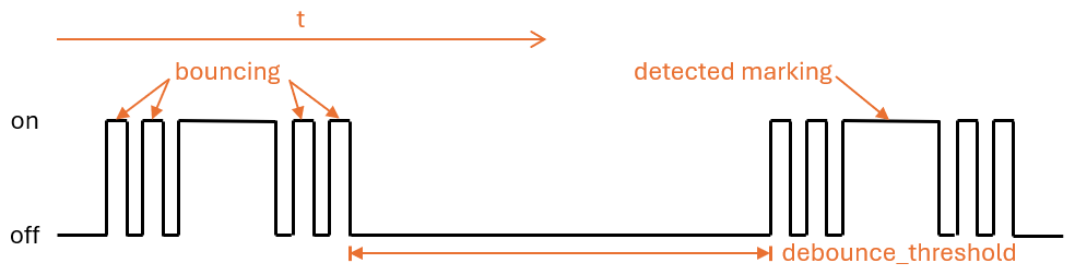
name : KalibrierungsmodusThe transition from non-marked to marked area and vice versa on the turntable can lead to a quick back and forth ("bouncing") of the identification state of the sensor, which occurs especially at slow rotary speeds and cannot be completely suppressed by the calibration. This bruise leads to falsified measurements and to avoid them, there are the following settings.
The debounce_threshold depressing threshold specifies the minimum time in milliseconds between falling and subsequent increasing flank. Only if the measured time is between the two flanks above the configured value is the sensor triggering into account. This type of depression works when using both the digital and the analog input signal of the infrared sensor.
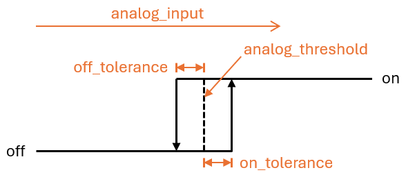
The two offset values off_tolerance and on_tolerance can be configured to use a hysteresis characteristic for the detection of the marked area on the turntable via the analog signal. This compensates for a "trembling" of the analog signal and thus minimizes a possible bruise of the identification state for the marked area on the turntable. This type of depression only works when using the analog input signal of the infrared sensor.
With a clever configuration of the update interval update_interval and the number of sampling per update ( samples ) for the analog sensor analog_input , the curve of the analog signal can be smoothed so far that short -term fluctuations are eliminated. However, it should be borne in mind that too large update intervals can lead to the fact that individual revolutions are no longer recognized at very high turning speeds, since the time between increasing and subsequent falling flank is smaller than the set update interval. This type of depression also only works when using the analog input signal of the infrared sensor.
In order to compensate for the meter state in the Ferraris component with the actual meter of the Ferraris current meter, the value of the consumption meter sensor can be explicitly overwritten. For this purpose, the two ferraris.set_energy_meter and ferraris.set_rotation_counter .
Tip
Usually only one of the two actions is necessary, depending on whether you want to put the meter in kilowatt hours or in number of revolutions.
Depending on whether the setting of the meter level should be handled by the user interface or automatically via automations and scripts, the actions can be used in different ways. Two possible application examples are described below, but there are other options that are not described here.
For this, for example, the following configuration steps are carried out (in this example to set the meter stand as a kilowatt hour value):
 number :
  - platform : template
    id : target_energy_value
    name : Manueller Zählerstand
    icon : mdi:counter
    unit_of_measurement : kWh
    device_class : energy
    entity_category : config
    mode : box
    optimistic : true
    min_value : 0
    max_value : 1000000
step : 0.01 button :
- platform : template
name : Verbrauchszähler überschreiben
icon : mdi:download
entity_category : config
on_press :
- ferraris.set_energy_meter :
id : ferraris_meter
value : !lambda |-
float val = id(target_energy_value).state;
return (val >= 0) ? val : 0; For this, for example, the following configuration steps are carried out:
ferraris.set_energy_meter campaign). api :
# ...
actions :
- action : set_energy_meter
variables :
target_value : float
then :
- ferraris.set_energy_meter :
id : ferraris_meter
value : !lambda |-
return (target_value >= 0)
? target_value
: 0;- id : ' 1234567890 '
alias : Zurücksetzen des Verbrauchszählers
trigger :
- platform : time
at : 00:00:00
condition :
- condition : template
value_template : ' {{ now().day == 1 }} '
action :
- action : esphome.ferraris_meter_set_energy_meter
data :
target_value : 0
mode : singleIn order not to reduce the lifespan of the flash memory on the ESP microcontroller, the Ferraris component does not save any data persistently in the flash. As a result, it cannot first remember the meter state over a restart of the microcontroller and the counter begins counting at 0 kWh at every boat. So after each restart, you would have to manually overwrite the meter scale by a value read on the Ferraris current meter. Since this is not very user -friendly, there is the possibility to persist the last meter state in Home Assistant and to transfer it to it when booting the microcontroller.
In order for this to work, the following configuration steps must be carried out, for example:
input_number.stromzaehler_letzter_wert ). number :
- platform : homeassistant
id : last_energy_value
entity_id : input_number.stromzaehler_letzter_wertenergy_start_value refers to the number component under 2. ferraris :
# ...
energy_start_value : last_energy_value- id : ' 1234567890 '
alias : Aktualisierung Verbrauchszähler-Cache
trigger :
- platform : state
entity_id :
- sensor.ferraris_meter_verbrauchszaehler
condition : []
action :
- action : input_number.set_value
target :
entity_id : input_number.stromzaehler_letzter_wert
data :
value : ' {{ states(trigger.entity_id) }} '
mode : singleenergy_meter in the YAML configuration file can also be created, which updates the number component under 2. However, this extends the processing time per revolution in the microcontroller and can lead to the fact that individual rounds of the turntable are not recorded in the case of very high power consumption (and therefore very high rotating speeds). Therefore, I recommend the variant with the automation in Home Assistant.Ferraris meter is an esphome component for creating an ESP firmware that uses an ESP microcontroller and an infrared sensor the number of rotations and the speed of the gymnastics of an analog ferraris electricity meter and to calculate the current electricity consumption and meter reading. Thesis value can then be sent to a home automation software search as home assistant for Further processing.
The software (including the documentation with the example hardware setup) is provided "as is", Without Warranty of Any Kind, Express or Implied, including but not limited to the Warranties of merchavity, Fitness for a Particular Purpose and Noninfringement. In No Event Shall the Authors Or Copyright Holders Be Lible for Any Claim, Damages or Other Liability, Whether in an action of contract, Tort or OtherWise, Arising from, out of or in Connection with or the use or other dealings in the software.
On the hardware side, only an ESP microcontroller (EG ESP8266 OR ESP32, including power supply) and an Infrared sensor (EG TCRT5000) are requested. An ESP8266 Microcontroller is Completely Suffed for the Pure Functionality of the Ferraris Meter. For the infrared sensor, there are ready-made TCRT5000-Based Breakout module with 3.3V-5V input voltage Available, which therefore have an adjustable resistor (potentiometer) to Calibrate the Digital Output of the Sensor. Thesis TCRT5000 Modules have 4 pins - vcc and gnd for the power supply of the sensor chip as well as a digital output d0 and an analog output a0.
Placing the Sensor on the cover Plate of the Ferraris Electricity Meter Requires A Little Skill and Precision Work. The infrared transmitter/receiver pair of the sensor must be aligned centrally above the turntable with millimeter precision and point in a straight line to the turntable.
The Ferraris Meter Component Basically Supports The Follow Setup Variants:
To build an esphome firmware, you have to creature a yaml -based configuration file. You can use one of the example configuration files proved in this repository as a starting point and adapt it to your needs.
In Principle, there are Two Ways to Build the Esphome Firmware:
What method You should choose Depends on How Familiar you are with esphome and Whether you prefer to work with a graphical user interface or the command line. In addition, the performance of the hosts on which you are building the firmware could play a role in Speeding Up the Process.
note
It is not necessary to fork this repository and do the adaptations to the example configuration Directly Inside the Forked Repository. Instead, it is sufficient to save and adapte the example configuration Locally or Store IT on your home assistant host (if you wish to build the esphome firmware with the esphome device compiler add-on).
The Following Sections Describe The Most Notable Components Contained in the firmware configuration file.
The ferraris component is essential and must be added in order to use its sensors.
As this is a Custom Component which is not part of esphome, it must be imported explicitly. The Easiest Way is to load the component Directly from this repository.
 external_components :
  - source : github://jensrossbach/esphome-ferraris-meter
    components : [ferraris]
Tip
In the Above Example, The Newest Version of the Component From The main Branch of the Repository is Loaded. However, I Recommend Using A version Number to Refer to a Released version in Order to have more control over which software version is used and to be ABLE to react better to "Breaking Changes". See the Example Configuration for How This Can Be Done.
The following generic configuration items can be configured:
| option | Type | Required | default | Description |
|---|---|---|---|---|
id | ID | No 1 | - | Ferraris Component Instance |
digital_input | Pin | YES 2 | - | GPIO PIN to which the digital output of the tcrt5000 modules is connected |
analog_input | ID | YES 2 | - | ADC sensor which reads out the pin connected to the analog output of the tcrt5000 modules |
analog_threshold | Number / ID 3 | NO | 50 | Threshold value for the detection of rotations via the analog input |
off_tolerance | Number / ID 3 | NO | 0 | Negative offset to the analog Threshold for the Falling Edge, See Section DeBouncing for Details |
on_tolerance | Number / ID 3 | NO | 0 | Positive offset to the analog Threshold for the Rising Edge, See Section DeBouncing for Details |
rotations_per_kwh | Number | NO | 75 | Number of Rotations of the turntable via kWh (that value is usually noted on the ferraris electricity meter) |
debounce_threshold | Number / ID 3 | NO | 400 | Minimum time in milliseconds falling and subsequent rising edge to take the rotation into account, see section deboOncing for details |
energy_start_value | ID | NO | - | Number Component Whose Value Will Be Used As Starting Value for the Energy Counter at Boot Time |
1 some use cases require the configuration element id .
2 ONLY ONE OF digital_input OR analog_input is request, depending on the hardware setup variant.
3 The Configuration Elements analog_threshold , off_tolerance , on_tolerance and debounce_threshold Expect Either a Static Number or the ID on a Number Component. The Latter Allows the Configuration of the Value Via the User Interface (EG, by Using A Template Number).
 ferraris :
  id : ferraris_meter
  digital_input : GPIO4
  rotations_per_kwh : 75
  debounce_threshold : 400
energy_start_value : last_energy_valueTo API component is required if the ESP Shall be integrated into home assistant. For the case that an alternative home automation software shall be used, a mqtt component has to be added instead. However, Certain Mechanisms Search as Manually Overwrriting the Energy Meter or Restoring the Last Meter Reading After A Restart (Lake Below for Details) wants that Possibly no Longer Work.
See Below Example for the Integration Into Home Assistant (With Encrypted API):
 api :
  encryption :
    key : !secret ha_api_key
And below to Example for Usage with an alternative home automation software via MQTT:
 mqtt :
  broker : 10.0.0.2
  username : !secret mqtt_user
password : !secret mqtt_passwordA WIFI Component Should be present, as OtherWise the Sensor Values Cannot Be Easily Transmitted to Another Computer.
 wifi :
  ssid : !secret wifi_ssid
password : !secret wifi_passwordThe Ferraris Component Provides Primary Sensors to Expose The Calculated Consumpto Values as Well as Diagnostic Sensors for the Calibration Mode. All sensors are optional and can be omitted if not needed.
The following primary sensors can be configured:
| sensor | Type | Device Class | State Class | Unit | Description |
|---|---|---|---|---|---|
power_consumption | numeric | power | measurement | W | Current Power Consumption |
energy_meter | numeric | energy | total_increasing | WH | Total Energy Consumption (Meter Reading) |
For detailed configuration options of each item, please refer to esphome sensor component configuration.
 sensor :
  - platform : ferraris
    power_consumption :
      name : Power consumption
    energy_meter :
name : Meter reading The following diagnostic sensors can be configured:
| sensor | Type | Description |
|---|---|---|
rotation_indicator | binary | Indicates if the mark on the turntable is in front of the infrared sensor (only works in calibration mode) |
For detailed configuration options of each item, please refer to ESPHome binary sensor component configuration.
 binary_sensor :
  - platform : ferraris
    rotation_indicator :
name : Rotation indicator For diagnostic purposes, the Ferraris component provides a switch with the name calibration_mode . It can be used to set the component to calibration mode (see section calibration for further information).
 switch :
  - platform : ferraris
    calibration_mode :
name : Calibration modeThe Ferraris component provides two actions for setting the energy meter reading and the rotation counter.
| Action | Description |
|---|---|
ferraris.set_energy_meter | Sets the energy meter reading to the provided value |
| parameter | Type | Range | Description |
|---|---|---|---|
value | float | >= 0 | Target value for the energy meter reading in kilowatt hours (kWh) |
note
Although the sensor for the current meter reading has the unit Wh (watt hours) , the action for overwriting the meter reading has the unit kWh (kilowatt hours) , as the analog Ferraris electricity meters usually also display the meter reading in this unit.
| Action | Description |
|---|---|
ferraris.set_rotation_counter | Sets the rotation counter to the provided value |
note
The action for setting the energy meter reading indirectly also sets the rotation counter as the Ferraris component internally works with rotations and not with watt hours or kilowatt hours.
| parameter | Type | Range | Description |
|---|---|---|---|
value | uint64 | >= 0 | Target value for the rotation counter in number of rotations |
This section describes various examples of usage for the Ferraris component.
In this variant, the digital output of the infrared sensor is used to detect rotations of the turntable. The analog output is not required, the other pins must be connected to the corresponding pins of the microcontroller. The 3.3V output of the ESP should be used for VCC and the digital output D0 must be connected to a free GPIO pin (eg GPIO4, corresponding to pin D2 on the D1 Mini).
The following breadboard schematic shows an example test setup using an ESP8266 D1 Mini development board as microcontroller.
The digital output signal of the infrared sensor must be calibrated via the potentiometer using a screwdriver; the two green LEDs on the back of the sensor help with this. The right-hand LED lights up continuously when the sensor is supplied with power. The left-hand LED lights up as long as no "obstacle" has been detected and goes out when the reflection has been interrupted. The latter is the state when the mark on the Ferraris electricity meter's turntable moves in front of the sensor. The adjustment of the potentiometer should therefore be set so that the left-hand LED just lights up when the marker is not in the range of the infrared transmitter/receiver pair and goes out as soon as the marker moves in front of it. This is only a very small range and it can be a little difficult to find this setting. To further assist with this process, the calibration mode can be enabled in the Ferraris Meter firmware, see section calibration for details.
Tip
In case you are unable to find an appropriate and working adjustment of the potentiometer, you can alternatively use the analog output of the infrared sensor, see next section.
On the software side, the pin which is connected to the digital output of the TCRT5000 module has to be configured for the Ferraris component in the YAML configuration file:
 ferraris :
  id : ferraris_meter
  digital_input : GPIO4
  # ...
Example configuration file: ferraris_meter_digital.yaml
In this variant, the analog output of the infrared sensor is used to detect rotations of the turntable. The digital output is not required, the other pins must be connected to the corresponding pins of the microcontroller. The 3.3V output of the ESP should be used for VCC and the analog output A0 must be connected to a free ADC pin (eg GPIO17, corresponding to pin A0 on the D1 Mini).
The following breadboard schematic shows an example test setup using an ESP8266 D1 Mini development board as microcontroller.
A calibration using the potentiometer on the TCRT5000 module is not needed. Instead, the threshold for the analog input and optionally the offset values for a hysteresis curve must be configured on the software side (see also section Debouncing further down). Here as well, the calibration mode of the Ferraris component could be helpful, see section calibration for details.
The threshold value analog_threshold controls when the analog signal is treated as "detected" (marked area of the turntable) and when it is treated as "not detected" (unmarked area of the turntable). If the value from the ADC sensor analog_input is greater than the threshold value, the marking is considered detected; if it is smaller than or equal to the threshold value, it is considered not detected.
On the software side, for instance, the following configuration steps must now be carried out:
 sensor :
  - platform : adc
    id : adc_input
    pin : GPIO17
    internal : true
    raw : true
    samples : 10
update_interval : 50ms number :
- platform : template
id : adc_threshold
name : ADC threshold
icon : mdi:speedometer-slow
entity_category : config
mode : box
optimistic : true
initial_value : 50
min_value : 0
max_value : 1000
step : 1analog_input refers to the ADC sensor created under 1. and the entry analog_threshold refers to the number component created under 2. ferraris :
id : ferraris_meter
analog_input : adc_input
analog_threshold : adc_threshold
# ...analog_threshold if the threshold value is already known and no longer needs to be configured/changed. In this case, step 2 can be omitted. ferraris :
# ...
analog_threshold : 45
# ... The configuration for the offset values off_tolerance and on_tolerance is very similar to the configuration of analog_threshold and therefore not explicitly shown in above example.
Example configuration file: ferraris_meter_analog.yaml
It is also possible to read more than one Ferraris electricity meter with a single ESP microcontroller. This requires multiple infrared sensors / TCRT5000 modules and additional free GPIO pins on the microcontroller. The TCRT5000 modules have to be connected to the voltage source of the ESP microcontroller via VCC and GND as described in the section Hardware Setup and the D0 outputs have to be connected to free GPIO pins on the ESP board.
note
Theoretically, the variant with the analog output of the infrared sensor can also be used, but the ADC-capable pins on the ESP microcontrollers are stronger limited than the pure digital pins. Especially the ESP8266, which has a single ADC only, would therefore not be suitable to support multiple infrared sensors via their analog outputs.
The following breadboard schematic shows an example of an example test setup with two TCRT5000 modules connected to an ESP8266 D1 Mini.
However, bear in mind that each additional infrared sensor increases the load on the microcontroller and brings the hardware closer to its limits, especially with very high rotation speeds of the turntables.
On the software side, for instance, the following configuration steps must now be carried out:
 ferraris :
  - id : ferraris_meter_1
    digital_input : GPIO4
    # ...
  - id : ferraris_meter_2
    digital_input : GPIO5
# ...ferraris_id configuration entry. sensor :
- platform : ferraris
ferraris_id : ferraris_meter_1
power_consumption :
name : Power consumption 1
energy_meter :
name : Meter reading 1
- platform : ferraris
ferraris_id : ferraris_meter_2
power_consumption :
name : Power consumption 2
energy_meter :
name : Meter reading 2
binary_sensor :
- platform : ferraris
ferraris_id : ferraris_meter_1
rotation_indicator :
name : Rotation indicator 1
- platform : ferraris
ferraris_id : ferraris_meter_2
rotation_indicator :
name : Rotation indicator 2
switch :
- platform : ferraris
ferraris_id : ferraris_meter_1
calibration_mode :
name : Calibration mode 1
- platform : ferraris
ferraris_id : ferraris_meter_2
calibration_mode :
name : Calibration mode 2Example configuration file: ferraris_meter_multi.yaml
During the positioning and alignment of the infrared sensor as well as the adjustment of the potentiometer or the analog threshold, it makes little sense to measure the rotations of the Ferraris electricity meter's turntable and calculate the consumption values, as the changes in state of the sensor do not correspond to the actual detection of the mark on the turntable. It is therefore possible to set the Ferraris component to calibration mode by turning on the calibration mode switch (see Actors). As long as the calibration mode is activated, no calculation of the consumption data is performed and the corresponding sensors (see Primary Sensors) are not changed. Instead, the diagnostic sensor for the rotation indication (see Diagnostic Sensors) is active and can additionally be used to assist with correct alignment. The sensor has the on state when the marker on the turntable is detected and the off state when it is not detected.
To be able to use the calibration mode, the components calibration_mode and rotation_indicator must be configured in the YAML file:
 binary_sensor :
  - platform : ferraris
    rotation_indicator :
      name : Rotation indicator

switch :
  - platform : ferraris
    calibration_mode :
name : Calibration modeThe transition from unmarked to marked area and vice versa on the turntable can lead to a rapid back and forth jump ("bouncing") in the detection state of the sensor, which occurs particularly at slow rotation speeds and cannot be completely suppressed by the calibration. This bouncing of the state leads to falsified measured values and to avoid this, the following settings can be applied.
The debounce threshold value debounce_threshold specifies the minimum time in milliseconds between falling and subsequent rising edge. The trigger from the sensor is only taken into account if the measured time between the two edges is above the configured value. This type of debouncing can be applied to both the variant using the digital as well as the analog input signal of the infrared sensor.
The two offset values off_tolerance and on_tolerance can be configured to use a hysteresis curve for the detection of the marked area on the turntable via the analog signal. This compensates the jitter of the analog signal and thus minimizes any possible bouncing of the detection status for the marked area on the turntable. This type of debouncing only works when using the analog input signal of the infrared sensor.
By carefully configuring the update interval update_interval and the number of samples per update ( samples ) for the analog sensor analog_input , the curve of the analog signal can be smoothed to such an extent that short-term fluctuations are eliminated. However, bear in mind that excessive update intervals can lead to individual rotations no longer being detected at very high rotation speeds, as the time between the rising and subsequent falling edge is then shorter than the set update interval. Also this type of debouncing only works when using the analog input signal of the infrared sensor.
To synchronize the meter reading in the Ferraris component with the actual meter reading of the Ferraris electricity meter, the value of the energy meter sensor can be explicitly overwritten. The two actions ferraris.set_energy_meter and ferraris.set_rotation_counter (see Actions) are provided for this purpose.
Tip
Usually, you need to use only one of the two actions, depending on whether you want to set the meter reading in kilowatt hours or in number of rotations.
The actions can be used in different ways, depending on whether the energy meter reading is to be set manually via the user interface or trigger-based via automations and scripts. Two possible usage examples are described below, but there are more possibilities existing which are not described here.
For instance, the following configuration steps are carried out (in this example to overwrite the energy meter with a kilowatt hours value):
 number :
  - platform : template
    id : target_energy_value
    name : Manual meter reading
    icon : mdi:counter
    unit_of_measurement : kWh
    device_class : energy
    entity_category : config
    mode : box
    optimistic : true
    min_value : 0
    max_value : 1000000
step : 0.01 button :
- platform : template
name : Overwrite meter reading
icon : mdi:download
entity_category : config
on_press :
- ferraris.set_energy_meter :
id : ferraris_meter
value : !lambda |-
float val = id(target_energy_value).state;
return (val >= 0) ? val : 0; For instance, the following configuration steps are carried out:
ferraris.set_energy_meter is used). api :
# ...
actions :
- action : set_energy_meter
variables :
target_value : float
then :
- ferraris.set_energy_meter :
id : ferraris_meter
value : !lambda |-
return (target_value >= 0)
? target_value
: 0;- id : ' 1234567890 '
alias : Reset energy meter reading
trigger :
- platform : time
at : 00:00:00
condition :
- condition : template
value_template : ' {{ now().day == 1 }} '
action :
- action : esphome.ferraris_meter_set_energy_meter
data :
target_value : 0
mode : singleIn order not to reduce the service life of the flash memory on the ESP microcontroller, the Ferraris component does not store any data persistently in the flash. As a result, it cannot remember the meter reading after a restart of the microcontroller and the meter starts counting at 0 kWh with every boot process. Therefore, the meter reading would have to be overwritten manually with a value read from the Ferraris electricity meter after each restart. As this is not very user-friendly, there is the option of persisting the last meter reading in Home Assistant and transferring it to the microcontroller when booting.
For this to work, the following configuration steps must be carried out:
input_number.electricity_meter_last_value ). number :
- platform : homeassistant
id : last_energy_value
entity_id : input_number.electricity_meter_last_valueenergy_start_value refers to the number component created under 2. ferraris :
# ...
energy_start_value : last_energy_value- id : ' 1234567890 '
alias : Update meter reading cache
trigger :
- platform : state
entity_id :
- sensor.ferraris_meter_energy
condition : []
action :
- action : input_number.set_value
target :
entity_id : input_number.electricity_meter_last_value
data :
value : ' {{ states(trigger.entity_id) }} '
mode : singleenergy_meter in the YAML configuration file which updates the number component created under 2 directly from ESPHome. However, this leads to a longer processing time per rotation in the microcontroller and may result in individual rotations of the turntable not being detected in the event of very high power consumption (and hence, very high rotation speeds). Therefore, I recommend the variant with the automation in Home Assistant.

