esphome ferraris meter
Release 1.4.1
注記
これはドイツ語版です。英語版の場合は、下にスクロールするか、ここをクリックしてください。
Ferraris Meterは、ESPファームウェアを作成するためのEsphomeコンポーネントであり、ESPマイクロコントローラーと赤外線センサーを使用して、アナログフェラーリスストリームメーターのターンテーブルの速度と回転を決定できます。これらの値は、さらなる処理のためにホームアシスタントなどのホームオートメーションソフトウェアに送信できます。
ソフトウェア(ハードウェアサンプル構造を使用したドキュメントを含む)は、デフォルトなしで提供され、表または暗黙の保証なしで提供されます。著者または著作権の所有者は、契約や責任訴訟、責任訴訟、不正な行為など、ソフトウェアまたはその他のソフトウェアまたはその他のショップに関連して発生するかどうかにかかわらず、請求、損害、またはその他の義務について決して責任を負いません。
ESPマイクロコントローラー(電圧供給を含むESP8266またはESP32など)と赤外線センサー(TCRT5000など)のみが必要です。 Ferrarisメーターの純粋な機能については、ESP8266でマイクロコントローラーとして完全に十分です。赤外線センサーの場合、3.3V-5V入力電圧を備えたTCRT5000ベースのブレークアウトモジュールが完成し、デジタル出力を較正するための制御可能な抵抗(ポテンティオメーター)もあります。これらのTCRT5000モジュールには、センサーチップの電源用の4つのピンVCCとGND、デジタル出力D0およびアナログ出力A0があります。
フェラーリの電流メーターのカバープレートにセンサーを配置する場合、少しのスキルと精度の作業が必要です。センサーの赤外線トランスミッター/受信者カップルは、ターンテーブル上で正確にミリメートルの中央で整列し、ターンテーブルをまっすぐに並べなければなりません。
原則として、Ferrarisメーターコンポーネントは、次の開発バリアントをサポートしています。
Esphomeファームウェアを作成するには、YAMLベースの構成ファイルを作成する必要があります。このリポジトリで提供されているサンプル構成ファイルのいずれかを出発点として使用して、ニーズに合わせて適応できます。
原則として、Esphomeファームウェアを構築するには2つの方法があります。
どの方法を選択する必要があるかは、Esphomeに対する信頼の信頼と、グラフィカルユーザーインターフェイスまたはコマンドラインで作業することを好むかどうかによって異なります。さらに、ファームウェアを構築するホストのパフォーマンスは、プロセスを加速する役割を果たす可能性があります。
注記
このリポジトリ( "Forken")をコピーしたり、コピーされたリポジトリのサンプル構成に適応する必要はありません。代わりに、サンプル構成を保存して適応させるか、ホームアシスタントホストの適応構成を取り外すだけで十分です(Esphomeデバイスコンパイラアドオンを使用してEsphomeファームウェアの作成が望ましい場合があります)。
次のセクションでは、ファームウェア構成ファイルに含まれる最も重要なコンポーネントについて説明します。
コンポーネントフェラーリは不可欠であり、センサーを使用するために追加する必要があります。
Esphomeの一部ではないカスタムコンポーネントであるため、明示的にインポートする必要があります。最も簡単な方法は、このリポジトリからコンポーネントを直接ロードすることです。
 external_components :
  - source : github://jensrossbach/esphome-ferraris-meter
    components : [ferraris]
ヒント
上記の例では、コンポーネントの最新のステータスがリポジトリのmainブランチから招待されています。ただし、バージョン番号を使用してリリースされたスタンドを参照して、どのソフトウェアスタンドが使用されているかをより詳細に制御し、「変化を破る」ことに対応できるようにすることをお勧めします。これをどのように実行するかをサンプル構成を参照してください。
次の汎用設定を構成できます。
| オプション | タイプ | 必要です | 標準 | 説明 |
|---|---|---|---|---|
id | id | いいえ1 | - | Ferrarisコンポーネントのインスタンス |
digital_input | ピン | はい2 | - | TCRT5000モジュールのデジタル出力が接続されているGPIOピン |
analog_input | id | はい2 | - | TCRT5000モジュールのアナログ出力に接続されたピンを読み取るADCセンサー |
analog_threshold | 番号 / ID 3 | いいえ | 50 | アナログ入力を介した革命の検出のしきい値 |
off_tolerance | 番号 / ID 3 | いいえ | 0 | 下向きの脇腹のアナログしきい値の値の負のオフセット、詳細については憂鬱なセクションを参照してください |
on_tolerance | 番号 / ID 3 | いいえ | 0 | 上昇面のアナログしきい値の値の正のオフセット、詳細については抑圧されているセクションを参照してください |
rotations_per_kwh | 番号 | いいえ | 75 | kWhあたりのターンテーブルの回転数(値はフェラーリの電流メーターに記載されています) |
debounce_threshold | 番号 / ID 3 | いいえ | 400 | 革命が考慮されるように、落下とその後の脇腹の増加の間のミリ秒単位での最小時間については、詳細についてはセクション奪取を参照してください |
energy_start_value | id | いいえ | - | 消費量計の開始値としてブートに値が使用される数値コンポーネント |
1特定のアプリケーションには、構成要素id必要です。
2ハードウェア開発バリアントに応じて、2つの構成要素のうち1 analog_input digital_inputが必要です。
3構成要素analog_threshold 、 off_tolerance 、 on_tolerance 、 debounce_thresholdは、固定番号または番号コンポーネントのIDを期待します。後者は、ユーザーインターフェイスを介して値を構成できるようにします(たとえば、テンプレート番号コンポーネントを使用して)。
 ferraris :
  id : ferraris_meter
  digital_input : GPIO4
  rotations_per_kwh : 75
  debounce_threshold : 400
energy_start_value : last_energy_valueESPがホームアシスタントに統合される場合、APIコンポーネントが必要です。代替ホームオートメーションソフトウェアを使用する場合は、代わりにMQTTコンポーネントを追加する必要があります。ただし、メータースタンドの上書きや再起動後の最後のメータースケールの復元などの特定のメカニズム(詳細については以下を参照)が機能しなくなりました。
以下は、ホームアシスタント(および暗号化されたAPI)との統合の例です。
 api :
  encryption :
    key : !secret ha_api_key
そして、MQTTを使用した代替ホームオートメーションソフトウェアでの使用の例を次に示します。
 mqtt :
  broker : 10.0.0.2
  username : !secret mqtt_user
password : !secret mqtt_passwordWiFiコンポーネントを使用できる必要があります。そうしないと、センサー値を別のデバイスに簡単に転送できません。
 wifi :
  ssid : !secret wifi_ssid
password : !secret wifi_passwordFerrarisコンポーネントには、計算された消費値とキャリブレーションモードの診断センサーを出力するプライマリセンサーがあります。すべてのセンサーはオプションであり、必要でない場合は除外できます。
次のプライマリセンサーを構成できます。
| センサー | タイプ | デバイスクラス | 州クラス | ユニット | 説明 |
|---|---|---|---|---|---|
power_consumption | 数値 | power | measurement | w | 現在の消費電力 |
energy_meter | 数値 | energy | total_increasing | WH | 総消費量(電力メーター/メーター状態) |
Esphomeセンサーコンポーネントのドキュメントで、個々の要素の構成オプションに関する詳細情報を見つけることができます。
 sensor :
  - platform : ferraris
    power_consumption :
      name : Momentanverbrauch
    energy_meter :
name : Verbrauchszähler 次の診断センサーを構成できます。
| センサー | タイプ | 説明 |
|---|---|---|
rotation_indicator | バイナリ | ターンテーブルのマーキングが赤外線センサーのすぐ前にあるかどうかを示します(キャリブレーションモードでのみ動作します) |
Esphomeバイナリセンサーコンポーネントのドキュメントで、個々の要素の構成オプションに関する詳細情報を見つけることができます。
 binary_sensor :
  - platform : ferraris
    rotation_indicator :
name : Umdrehungsindikator診断のために、Ferrarisコンポーネントにはスイッチがあります。これにはcalibration_modeという名前があり、コンポーネントをキャリブレーションモードに配置するために使用できます(詳細については、セクションのキャリブレーションを参照)。
 switch :
  - platform : ferraris
    calibration_mode :
name : KalibrierungsmodusFerrarisコンポーネントは、メータースケールを設定し、遷移カウンターを設定するための2つのアクションを提供します。
| アクション | 説明 |
|---|---|
ferraris.set_energy_meter | 指定された値にメーター状態を配置します |
| パラメーター | タイプ | エリア | 説明 |
|---|---|---|---|
value | float | > = 0 | キロワット時間(kWh)のメーター状態の目標値 |
注記
現在のメーター状態のセンサーにはユニットWH(ワット時間)がありますが、メータースタンドを上書きするアクションはユニットKWH(キロワット時間)を使用します。
| アクション | 説明 |
|---|---|
ferraris.set_rotation_counter | 指定された値に回転カウンターを配置します |
注記
フェラリスコンポーネントはワット時間やキロワット時間ではなく、回転とは内部的に機能するため、メータースタンドを間接的に設定するためのアクションも回転カウンターを設定します。
| パラメーター | タイプ | エリア | 説明 |
|---|---|---|---|
value | uint64 | > = 0 | 数革命の売上高カウンターの目標値 |
このセクションでは、Ferrarisコンポーネントのさまざまなアプリケーションの例について説明します。
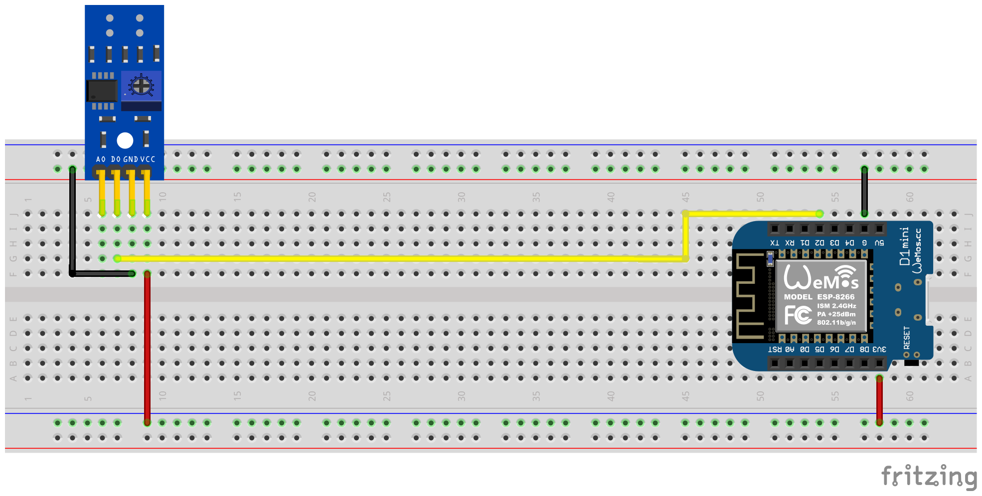
このバリアントでは、赤外線センサーのデジタル出力を使用して、ターンテーブルの回転を識別します。アナログ出力は必要ありません。他のピンは、マイクロコントローラーの対応するピンに接続する必要があります。 VCCの場合、ESPの3.3V出力を使用し、デジタル出力D0をフリーGPIOピンに接続する必要があります(GPIO4、D1 MiniのピンD2に対応します)。
次のプラグイン回路図は、MicrocontrollerとしてESP8266 D1 MINI開発ボードを使用した実験的セットアップの例を示しています。
ドライバーの助けを借りて、デジタル出力信号をポテンショメータを介して校正する必要があります。センサーの背面にある2つの緑色のLEDがヘルプされます。センサーに電気が供給されると、右のLEDが永久に輝きます。 「障害」が認識されておらず、反射が中断されたときに期限切れになっている限り、左のLEDは輝きます。後者は、フェラーリの電流メーターのターンテーブルのマーキングがセンサーの前でさまようときの状態です。したがって、ポテンショメータは、マーカーがその前に押し込むとすぐに、マーキングが赤外線送信者/受信者カップルの領域にないときに左のLEDがまだ輝くように設定する必要があります。これは非常に小さな領域であり、この設定を見つけるのは少し難しい場合があります。このプロセスの追加サポートについては、Ferraris Meterファームウェアでキャリブレーションモードをアクティブにすることができます。詳細については、キャリブレーションのセクションを参照してください。
ヒント
ポテンショメータに適した機能設定を見つけることができない場合は、赤外線センサーのアナログ出力を使用して使用できます。次のセクションを参照してください。
ソフトウェア側は、TCRT5000モジュールのデジタル出力に接続されているPIN YAML構成ファイルのFerrarisコンポーネント用に構成する必要があります。
 ferraris :
  id : ferraris_meter
  digital_input : GPIO4
  # ...
構成の例: ferraris_meter_digital.yaml
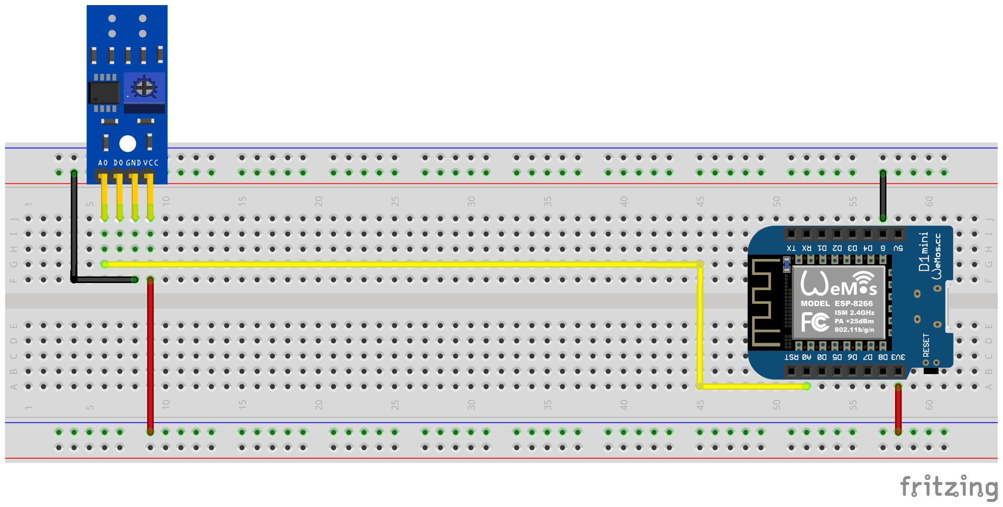
このバリアントでは、赤外線センサーのアナログ出力を使用して、ターンテーブルの回転を識別します。デジタル出力は必要ありません。他のピンは、マイクロコントローラーの対応するピンに接続する必要があります。 VCCの場合、ESPの3.3V出力を使用し、アナログ出力A0をフリーADCピンに接続する必要があります(たとえば、GPIO17はD1 MiniのピンA0に対応します)。
次のプラグイン回路図は、MicrocontrollerとしてESP8266 D1 MINI開発ボードを使用した実験的セットアップの例を示しています。
TCRT5000モジュールのポテンショメータによるキャリブレーションは不要になります。代わりに、ソフトウェア側をアナログ入力に対して構成する必要があります。ここでも、Ferrarisコンポーネントのキャリブレーションモードが役立ちます。詳細については、キャリブレーションのセクションをご覧ください。
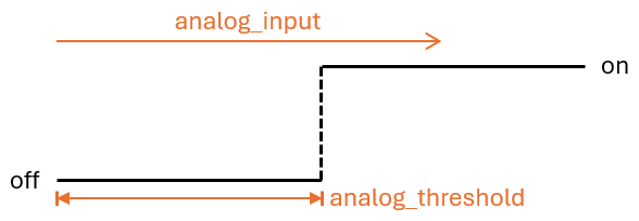
しきい値analog_thresholdは、アナログ信号が「認識された」(ターンテーブルのマークされた領域)として扱われる場合、および「認識されていない」(ターンテーブルのマークされていない領域ではない)として扱われたときに制御します。 ADCセンサーの値がanalog_inputよりも大きい場合、マーキングは認識されていると見なされ、それは小さくても同じで、認識されません。
これで、以下の構成手順を実行する必要があります。たとえば、ソフトウェア側:
 sensor :
  - platform : adc
    id : adc_input
    pin : GPIO17
    internal : true
    raw : true
    samples : 10
update_interval : 50ms number :
- platform : template
id : adc_threshold
name : ADC Schwellwert
icon : mdi:speedometer-slow
entity_category : config
mode : box
optimistic : true
initial_value : 50
min_value : 0
max_value : 1000
step : 1analog_threshold analog_input 。 ferraris :
id : ferraris_meter
analog_input : adc_input
analog_threshold : adc_threshold
# ...analog_thresholdの固定数値を指定することもできます。この場合、ステップ2は省略できます。 ferraris :
# ...
analog_threshold : 45
# ...オフセット値の構成off_toleranceおよびon_tolerance 、 analog_thresholdの構成と非常に似ているため、上記の例に明示的に示されていませんでした。
構成の例: ferraris_meter_analog.yaml
また、1つのESPマイクロコントローラーを備えた複数のフェラーリ電流カウンターを読むこともできます。これを行うには、さらに赤外線センサー / TCRT5000モジュールとマイクロコントローラーに追加の無料のGPIOピンが必要です。すでに説明されているように、TCRT5000モジュールはVCCおよびGNDを介してESPマイクロコントローラーの電圧源に接続されており、D0出力はそれぞれ無料のGPIOピンでESPボードに接続されています。
注記
理論的には、バリアントは赤外線センサーのアナログ出力で使用することもできますが、ESPマイクロコントローラーのADC対応ピンは、純粋なデジタルピンよりも制限されています。特に、ADCが1つしかないESP8266は、アナログ出力を介していくつかの赤外線センサーをサポートするのに適していません。
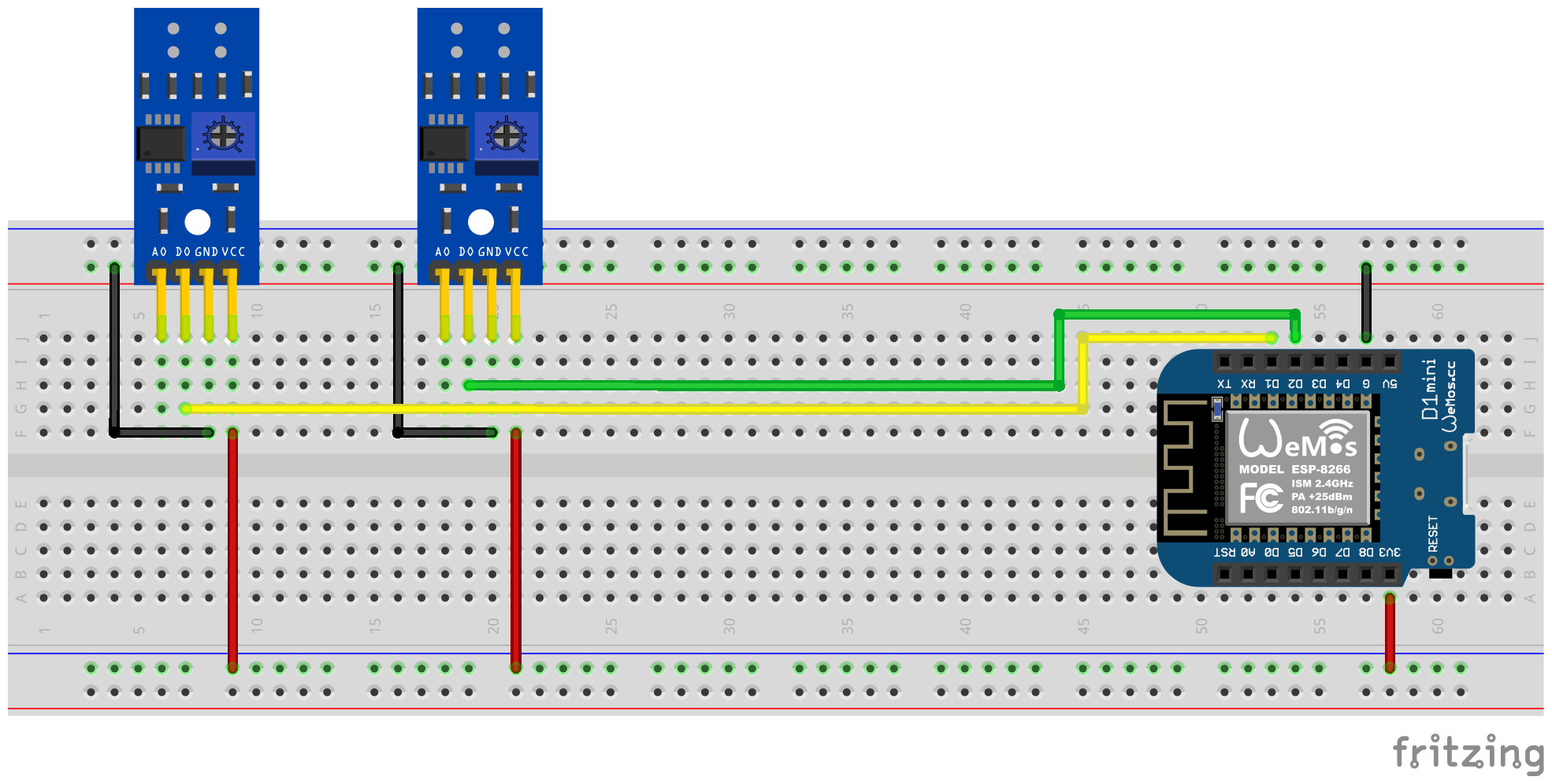
次のプラグイン回路図は、ESP8266 D1 MINIに接続された2つのTCRT5,000モジュールを備えたテストセットアップの例を示しています。
ただし、追加の追加の赤外線センサーがマイクロコントローラーの負荷を増加させることを念頭に置いておく必要があります。特に、ターンテーブルの非常に高速では、ハードウェアが制限に近づくことに留意する必要があります。
これで、以下の構成手順を実行する必要があります。たとえば、ソフトウェア側:
 ferraris :
  - id : ferraris_meter_1
    digital_input : GPIO4
    # ...
  - id : ferraris_meter_2
    digital_input : GPIO5
# ...ferraris_idを介してFerrarisコンポーネントの対応するインスタンスを乗算して割り当てる必要があります。 sensor :
- platform : ferraris
ferraris_id : ferraris_meter_1
power_consumption :
name : Momentanverbrauch 1
energy_meter :
name : Verbrauchszähler 1
- platform : ferraris
ferraris_id : ferraris_meter_2
power_consumption :
name : Momentanverbrauch 2
energy_meter :
name : Verbrauchszähler 2
binary_sensor :
- platform : ferraris
ferraris_id : ferraris_meter_1
rotation_indicator :
name : Umdrehungsindikator 1
- platform : ferraris
ferraris_id : ferraris_meter_2
rotation_indicator :
name : Umdrehungsindikator 2
switch :
- platform : ferraris
ferraris_id : ferraris_meter_1
calibration_mode :
name : Kalibrierungsmodus 1
- platform : ferraris
ferraris_id : ferraris_meter_2
calibration_mode :
name : Kalibrierungsmodus 2構成の例: ferraris_meter_multi.yaml
赤外線センサーの位置決めと整列、ポテンショメータまたはアナログのしきい値の調整中、フェラーリの電流メーターのターンテーブルの回転革命を測定し、センサーの条件の変化が実際のターンテーブルの検出に対応しないため、消費を計算することはほとんど意味がありません。したがって、キャリブレーションモードのためにスイッチをオンにすることにより、フェラーリコンポーネントをキャリブレーションモードに配置する可能性があります(アクチュエータを参照)。キャリブレーションモードがアクティブになっている限り、消費データの計算は実行されず、対応するセンサー(プライマリセンサーを参照)は変更されません。代わりに、回転表示の診断センサー(診断センサーを参照)がアクティブであり、正しいアライメントをサポートするためにも使用できます。センサーは、マークがターンテーブルで認識され、マーキングが認識されていない場合にマークが認識され、 off状態にonています。
キャリブレーションモードを使用できるようにするには、コンポーネントcalibration_modeとrotation_indicator YAMLファイルで構成する必要があります。
 binary_sensor :
  - platform : ferraris
    rotation_indicator :
      name : Umdrehungsindikator

switch :
  - platform : ferraris
    calibration_mode :
name : Kalibrierungsmodusマークされていない領域からマークされた領域への移行は、ターンテーブルの逆の範囲で、センサーの識別状態の迅速な前後(「バウンス」)につながる可能性があります。この打撲傷は偽造された測定につながり、それらを回避するために、次の設定があります。
debounce_threshold圧迫したしきい値は、下向きとその後の増加面の間のミリ秒単位で最小時間を指定します。測定された時間が、構成された値の上の2つのフランクの間にある場合にのみ、センサーが考慮されるセンサーがあります。このタイプのうつ病は、赤外線センサーのデジタル入力信号とアナログ入力信号の両方を使用する場合に機能します。
2つのオフセット値off_toleranceとon_tolerance 、アナログ信号を介してターンテーブル上のマークされた領域の検出にヒステリシス特性を使用するように構成できます。これは、アナログ信号の「震え」を補償し、ターンテーブルのマークされた領域の識別状態の打撲の可能性を最小限に抑えます。このタイプのうつ病は、赤外線センサーのアナログ入力信号を使用する場合にのみ機能します。
更新間隔のupdate_intervalの巧妙な構成と、アナログセンサーanalog_inputのアップデートごとのサンプリング数( samples )により、アナログ信号の曲線は、短期の変動が排除されるように滑らかにすることができます。ただし、アップデート間隔が大きすぎると、個々の革命が非常に高い回転速度で認識されなくなる可能性があることを念頭に置いておく必要があります。これは、増加してからの下向き側面の間の時間が設定された更新間隔よりも小さいためです。このタイプのうつ病は、赤外線センサーのアナログ入力信号を使用する場合にのみ機能します。
フェラリス電流メーターの実際のメーターを使用してフェラーリコンポーネントのメーター状態を補うために、消費メーターセンサーの値を明示的に上書きすることができます。この目的のために、2つのferraris.set_energy_meterとferraris.set_rotation_counter 。
ヒント
通常、メーターをキロワットの時間に配置するか、革命数に配置するかによって、2つのアクションのうち1つだけが必要です。
メーターレベルの設定をユーザーインターフェイスによって処理するか、自動化とスクリプトを介して自動的に処理する必要があるかどうかに応じて、アクションはさまざまな方法で使用できます。 2つの可能なアプリケーションの例を以下に説明しますが、ここでは説明されていない他のオプションがあります。
このため、たとえば、次の構成手順が実行されます(この例では、メータースタンドをキロワット時間の値として設定するため):
 number :
  - platform : template
    id : target_energy_value
    name : Manueller Zählerstand
    icon : mdi:counter
    unit_of_measurement : kWh
    device_class : energy
    entity_category : config
    mode : box
    optimistic : true
    min_value : 0
    max_value : 1000000
step : 0.01 button :
- platform : template
name : Verbrauchszähler überschreiben
icon : mdi:download
entity_category : config
on_press :
- ferraris.set_energy_meter :
id : ferraris_meter
value : !lambda |-
float val = id(target_energy_value).state;
return (val >= 0) ? val : 0; このため、たとえば、次の構成手順が実行されます。
ferraris.set_energy_meterキャンペーン)。 api :
# ...
actions :
- action : set_energy_meter
variables :
target_value : float
then :
- ferraris.set_energy_meter :
id : ferraris_meter
value : !lambda |-
return (target_value >= 0)
? target_value
: 0;- id : ' 1234567890 '
alias : Zurücksetzen des Verbrauchszählers
trigger :
- platform : time
at : 00:00:00
condition :
- condition : template
value_template : ' {{ now().day == 1 }} '
action :
- action : esphome.ferraris_meter_set_energy_meter
data :
target_value : 0
mode : singleESPマイクロコントローラーのフラッシュメモリの寿命を削減しないために、Ferrarisコンポーネントはフラッシュにデータを永続的に保存しません。その結果、マイクロコントローラーの再起動でメーター状態を最初に思い出せず、カウンターはすべてのボートで0 kWhでカウントを開始します。そのため、再起動するたびに、フェラーリの電流メーターで読み取られた値によってメータースケールを手動で上書きする必要があります。これは非常にユーザーではないため、ホームアシスタントの最後のメーター状態を維持し、マイクロコントローラーを起動するときにそれを転送する可能性があります。
これが機能するためには、次のような構成手順を実行する必要があります。
input_number.stromzaehler_letzter_wert )。 number :
- platform : homeassistant
id : last_energy_value
entity_id : input_number.stromzaehler_letzter_wertenergy_start_value 2未満の数値を指します。 ferraris :
# ...
energy_start_value : last_energy_value- id : ' 1234567890 '
alias : Aktualisierung Verbrauchszähler-Cache
trigger :
- platform : state
entity_id :
- sensor.ferraris_meter_verbrauchszaehler
condition : []
action :
- action : input_number.set_value
target :
entity_id : input_number.stromzaehler_letzter_wert
data :
value : ' {{ states(trigger.entity_id) }} '
mode : singleenergy_meterのセンサー自動化も作成できます。これにより、2未満のコンポーネントが更新されます。ただし、マイクロコントローラーの革命ごとの処理時間が延長され、ターンタイブルの個々のラウンドが非常に高い回転速度の場合に記録されないという事実につながる可能性があります。したがって、ホームアシスタントの自動化を備えたバリアントをお勧めします。Ferraris Meterは、ESPマイクロコントローラーと赤外線センサーを使用して、アナログフェラリス電気メーターの体操の速度を赤外線センサーに使用し、現在の電力消費とメーターの読み取り値を計算するESPHOMEコンポーネントです。その後、論文の値を、さらに処理するためにホームアシスタントとしてホームオートメーションソフトウェア検索に送信できます。
ソフトウェア(ハードウェアのサンプルセットアップを含むドキュメントを含む)は、「現状のまま」で提供されます。これは、特定の目的、および非侵害の保証を含むがこれらに限定されない、明示的または暗示されています。いかなる場合でも、著者または著作権所有者は、契約、不法行為、またはその他の訴訟、その他、またはソフトウェアの使用または使用またはその他の取引に起因する請求、損害、またはその他の責任について識別することはありません。
ハードウェア側では、ESPマイクロコントローラー(電源を含むESP8266またはESP32など)と赤外線センサー(TCRT5000など)のみが要求されます。 ESP8266マイクロコントローラーは、フェラーリメーターの純粋な機能に完全に十分です。赤外線センサーには、利用可能な3.3V-5V入力電圧を備えた既製のTCRT5000ベースのブレークアウトモジュールがあります。したがって、センサーのデジタル出力を調整するための調整可能な抵抗器(ポテンティオメーター)があります。論文TCRT5000モジュールには、センサーチップの電源用のVCCとGND、デジタル出力D0およびアナログ出力A0の4つのピンがあります。
フェラーリの電気メーターのカバープレートにセンサーを置くには、少しのスキルと精度の作業が必要です。センサーの赤外線送信機/受信機ペアは、ターンテーブルの上に中央に並べてミリメートルの精度で整列し、ターンテーブルに直線でポイントする必要があります。
Ferrarisメーターコンポーネントは、基本的にフォローセットアップバリアントをサポートしています。
Esphomeファームウェアを構築するには、YAMLベースの構成ファイルを作成する必要があります。このリポジトリで証明された例の構成ファイルのいずれかを出発点として使用し、ニーズに合わせて適応させることができます。
原則として、Esphomeファームウェアを構築するには2つの方法があります。
選択する方法は、Esphomeにどれだけ慣れているか、グラフィカルユーザーインターフェイスまたはコマンドラインで作業することを好むかどうかによって異なります。さらに、ファームウェアを構築しているホストのパフォーマンスは、プロセスをスピードアップする上で役割を果たす可能性があります。
注記
このリポジトリを分岐して、フォークリポジトリ内のサンプル構成への適応を行う必要はありません。代わりに、構成のサンプルをローカルで保存およびadapteするか、ホームアシスタントホストに保存するだけで十分です(Esphomeデバイスコンパイラアドオンを使用してEsphomeファームウェアを構築する場合)。
次のセクションでは、ファームウェア構成ファイルに含まれる最も注目すべきコンポーネントについて説明します。
フェラーリコンポーネントは不可欠であり、センサーを使用するために追加する必要があります。
これはEsphomeの一部ではないカスタムコンポーネントであるため、明示的にインポートする必要があります。最も簡単な方法は、このリポジトリからコンポーネントを直接ロードすることです。
 external_components :
  - source : github://jensrossbach/esphome-ferraris-meter
    components : [ferraris]
ヒント
上記の例では、リポジトリのmainブランチのコンポーネントの最新バージョンがロードされます。ただし、バージョン番号を使用してリリースされたバージョンを参照して、どのソフトウェアバージョンを使用しているかをより制御し、「変更を破る」ためによりよく反応できるようにすることをお勧めします。これをどのように実行するかについては、例の構成を参照してください。
次の汎用構成項目を構成できます。
| オプション | タイプ | 必須 | デフォルト | 説明 |
|---|---|---|---|---|
id | id | いいえ1 | - | Ferrarisコンポーネントインスタンス |
digital_input | ピン | はい2 | - | TCRT5000モジュールのデジタル出力が接続されているGPIOピン |
analog_input | id | はい2 | - | TCRT5000モジュールのアナログ出力に接続されたピンを読み取るADCセンサー |
analog_threshold | 番号 / ID 3 | いいえ | 50 | アナログ入力を介した回転の検出のしきい値値 |
off_tolerance | 番号 / ID 3 | いいえ | 0 | 下向きのエッジのアナログしきい値に対する負のオフセット、詳細についてはデバウンスのセクションを参照してください |
on_tolerance | 番号 / ID 3 | いいえ | 0 | 立ち上がりエッジのアナログしきい値に対する正のオフセット、詳細についてはデバウンスのセクションを参照してください |
rotations_per_kwh | 番号 | いいえ | 75 | KWH経由のターンテーブルの回転数(その値は通常、フェラーリの電気メーターに記載されています) |
debounce_threshold | 番号 / ID 3 | いいえ | 400 | ミリ秒の最小時間が下落し、その後の立ち上がりエッジが回転を考慮します。詳細については、セクションDeBooncingを参照してください |
energy_start_value | id | いいえ | - | ブート時間にエネルギーカウンターの開始値として値が使用される番号コンポーネント |
1一部のユースケースでは、構成要素idが必要です。
2ハードウェアのセットアップバリアントに応じて、 digital_inputまたはanalog_inputの1つのみが要求です。
3構成要素analog_threshold 、 off_tolerance 、 on_tolerance 、 debounce_thresholdは、数値コンポーネントの静的番号またはIDを期待します。後者を使用すると、ユーザーインターフェイスを介して値の構成を許可します(テンプレート番号を使用するなど)。
 ferraris :
  id : ferraris_meter
  digital_input : GPIO4
  rotations_per_kwh : 75
  debounce_threshold : 400
energy_start_value : last_energy_valueESPがホームアシスタントに統合される場合、APIコンポーネントが必要です。代替ホームオートメーションソフトウェアを使用する場合は、代わりにMQTTコンポーネントを追加する必要があります。ただし、特定のメカニズムは、エネルギーメーターを手動で上書きしたり、再起動後に最後のメーターの読み取り値を復元したりするように検索します(詳細のために以下の湖)。
以下の例を参照してください(暗号化されたAPIを使用)ホームアシスタントへの統合:
 api :
  encryption :
    key : !secret ha_api_key
以下に、MQTTを介した代替ホームオートメーションソフトウェアで使用するための例:
 mqtt :
  broker : 10.0.0.2
  username : !secret mqtt_user
password : !secret mqtt_passwordそれ以外の場合は、センサー値を別のコンピューターに簡単に送信できないため、WiFiコンポーネントが存在する必要があります。
 wifi :
  ssid : !secret wifi_ssid
password : !secret wifi_passwordFerrarisコンポーネントは、キャリブレーションモードの診断センサーだけでなく、計算された消費値を公開するための一次センサーを提供します。すべてのセンサーはオプションであり、必要でない場合は省略できます。
次のプライマリセンサーを構成できます。
| センサー | タイプ | デバイスクラス | 州クラス | ユニット | 説明 |
|---|---|---|---|---|---|
power_consumption | 数値 | power | measurement | w | 現在の消費電力 |
energy_meter | 数値 | energy | total_increasing | WH | 総エネルギー消費(メーターリーディング) |
各アイテムの詳細な構成オプションについては、Esphomeセンサーコンポーネントの構成を参照してください。
 sensor :
  - platform : ferraris
    power_consumption :
      name : Power consumption
    energy_meter :
name : Meter reading 次の診断センサーを構成できます。
| センサー | タイプ | 説明 |
|---|---|---|
rotation_indicator | バイナリ | ターンテーブルのマークが赤外線センサーの前にあるかどうかを示します(キャリブレーションモードでのみ動作します) |
各アイテムの詳細な構成オプションについては、Esphomeバイナリセンサーコンポーネントの構成を参照してください。
 binary_sensor :
  - platform : ferraris
    rotation_indicator :
name : Rotation indicator診断のために、Ferrarisコンポーネントは、名前calibration_modeという名前のスイッチを提供します。コンポーネントをキャリブレーションファッションに設定するために使用できます(詳細については、セクションのキャリブレーションを参照してください)。
 switch :
  - platform : ferraris
    calibration_mode :
name : Calibration modeFerrarisコンポーネントは、エネルギーメーターの読み取りと回転カウンターを設定するための2つのアクションを提供します。
| アクション | 説明 |
|---|---|
ferraris.set_energy_meter | エネルギーメーターの読み取り値を提供された値に設定します |
| パラメーター | タイプ | 範囲 | 説明 |
|---|---|---|---|
value | float | > = 0 | キロワット時間(kWh)でのエネルギーメーターの読み取り値の目標値 |
注記
現在のメーター読み取りのセンサーにはユニットがありますが(ワット時間) 、メーターの読み取り値をオーバードライブするためのアクションには、アナログフェラリス電気メーターが通常このユニットにメーターの読み取り値を表示するため、ユニットKWH(キロワット時間)があります。
| アクション | 説明 |
|---|---|
ferraris.set_rotation_counter | 回転カウンターを提供された値に設定します |
注記
エネルギーメーターを設定するためのアクションは間接的に読み取り、フェラリスコンポーネントとしての回転カウンターが、ワット時間やキロワット時間ではなく、ローテーションで内部的に機能します。
| パラメーター | タイプ | 範囲 | 説明 |
|---|---|---|---|
value | uint64 | > = 0 | 回転数の回転カウンターの目標値 |
このセクションでは、Ferrarisコンポーネントの使用例について説明します。
このバリアントでは、赤外線センサーのデジタル出力を使用して、ターンテーブルの回転を検出します。アナログ出力は必要ありません。他のピンは、マイクロコントローラーの対応するピンに接続する必要があります。 ESPの3.3V出力はVCCに使用する必要があり、デジタル出力D0はフリーGPIOピン(例:D1 MiniのピンD2に対応)に接続する必要があります。
次のブレッドボード概略図は、ESP8266 D1 Mini開発ボードをマイクロコントローラーとして使用したテストセットアップの例を示しています。
赤外線センサーのデジタル出力信号は、脚本家を使用してポテンショメータを介して較正する必要があります。センサーの背面にある2つの緑色のLEDは、これに役立ちます。センサーに電力が供給されると、右手LEDが連続的に点灯します。 「障害物」が検出されず、反射が中断されたときに消える限り、左側のLEDが点灯します。後者は、フェラーリの電気メーターのターンテーブルのマークがセンサーの前で動く状態です。したがって、ポテンショメータシェッドの調整は、マーカーが赤外線トランスミッター/レシーバーペアの範囲にないときに左手LEDが点灯し、マーカーがその前を移動するときに消えるようにするため。これは非常に小さな範囲であり、この設定を見つけるのは少し難しい場合があります。 To Further Assist with this Process, the Calibration Mode Can Be Enabled In The Ferraris Meter Firmware, See Section Calibration for Details.
ヒント
In case you are unable to find an appropriate and working adjustment of the potentiometer, you can alternatively use the analog output of the infrared sensor, see next section.
On the software side, the pin which is connected to the digital output of the TCRT5000 module has to be configured for the Ferraris component in the YAML configuration file:
 ferraris :
  id : ferraris_meter
  digital_input : GPIO4
  # ...
Example configuration file: ferraris_meter_digital.yaml
In this variant, the analog output of the infrared sensor is used to detect rotations of the turntable. The digital output is not required, the other pins must be connected to the corresponding pins of the microcontroller. The 3.3V output of the ESP should be used for VCC and the analog output A0 must be connected to a free ADC pin (eg GPIO17, corresponding to pin A0 on the D1 Mini).
The following breadboard schematic shows an example test setup using an ESP8266 D1 Mini development board as microcontroller.
A calibration using the potentiometer on the TCRT5000 module is not needed. Instead, the threshold for the analog input and optionally the offset values for a hysteresis curve must be configured on the software side (see also section Debouncing further down). Here as well, the calibration mode of the Ferraris component could be helpful, see section calibration for details.
The threshold value analog_threshold controls when the analog signal is treated as "detected" (marked area of the turntable) and when it is treated as "not detected" (unmarked area of the turntable). If the value from the ADC sensor analog_input is greater than the threshold value, the marking is considered detected; if it is smaller than or equal to the threshold value, it is considered not detected.
On the software side, for instance, the following configuration steps must now be carried out:
 sensor :
  - platform : adc
    id : adc_input
    pin : GPIO17
    internal : true
    raw : true
    samples : 10
update_interval : 50ms number :
- platform : template
id : adc_threshold
name : ADC threshold
icon : mdi:speedometer-slow
entity_category : config
mode : box
optimistic : true
initial_value : 50
min_value : 0
max_value : 1000
step : 1analog_input refers to the ADC sensor created under 1. and the entry analog_threshold refers to the number component created under 2. ferraris :
id : ferraris_meter
analog_input : adc_input
analog_threshold : adc_threshold
# ...analog_threshold if the threshold value is already known and no longer needs to be configured/changed. In this case, step 2 can be omitted. ferraris :
# ...
analog_threshold : 45
# ... The configuration for the offset values off_tolerance and on_tolerance is very similar to the configuration of analog_threshold and therefore not explicitly shown in above example.
Example configuration file: ferraris_meter_analog.yaml
It is also possible to read more than one Ferraris electricity meter with a single ESP microcontroller. This requires multiple infrared sensors / TCRT5000 modules and additional free GPIO pins on the microcontroller. The TCRT5000 modules have to be connected to the voltage source of the ESP microcontroller via VCC and GND as described in the section Hardware Setup and the D0 outputs have to be connected to free GPIO pins on the ESP board.
注記
Theoretically, the variant with the analog output of the infrared sensor can also be used, but the ADC-capable pins on the ESP microcontrollers are stronger limited than the pure digital pins. Especially the ESP8266, which has a single ADC only, would therefore not be suitable to support multiple infrared sensors via their analog outputs.
The following breadboard schematic shows an example of an example test setup with two TCRT5000 modules connected to an ESP8266 D1 Mini.
However, bear in mind that each additional infrared sensor increases the load on the microcontroller and brings the hardware closer to its limits, especially with very high rotation speeds of the turntables.
On the software side, for instance, the following configuration steps must now be carried out:
 ferraris :
  - id : ferraris_meter_1
    digital_input : GPIO4
    # ...
  - id : ferraris_meter_2
    digital_input : GPIO5
# ...ferraris_id configuration entry. sensor :
- platform : ferraris
ferraris_id : ferraris_meter_1
power_consumption :
name : Power consumption 1
energy_meter :
name : Meter reading 1
- platform : ferraris
ferraris_id : ferraris_meter_2
power_consumption :
name : Power consumption 2
energy_meter :
name : Meter reading 2
binary_sensor :
- platform : ferraris
ferraris_id : ferraris_meter_1
rotation_indicator :
name : Rotation indicator 1
- platform : ferraris
ferraris_id : ferraris_meter_2
rotation_indicator :
name : Rotation indicator 2
switch :
- platform : ferraris
ferraris_id : ferraris_meter_1
calibration_mode :
name : Calibration mode 1
- platform : ferraris
ferraris_id : ferraris_meter_2
calibration_mode :
name : Calibration mode 2Example configuration file: ferraris_meter_multi.yaml
During the positioning and alignment of the infrared sensor as well as the adjustment of the potentiometer or the analog threshold, it makes little sense to measure the rotations of the Ferraris electricity meter's turntable and calculate the consumption values, as the changes in state of the sensor do not correspond to the actual detection of the mark on the turntable. It is therefore possible to set the Ferraris component to calibration mode by turning on the calibration mode switch (see Actors). As long as the calibration mode is activated, no calculation of the consumption data is performed and the corresponding sensors (see Primary Sensors) are not changed. Instead, the diagnostic sensor for the rotation indication (see Diagnostic Sensors) is active and can additionally be used to assist with correct alignment. The sensor has the on state when the marker on the turntable is detected and the off state when it is not detected.
To be able to use the calibration mode, the components calibration_mode and rotation_indicator must be configured in the YAML file:
 binary_sensor :
  - platform : ferraris
    rotation_indicator :
      name : Rotation indicator

switch :
  - platform : ferraris
    calibration_mode :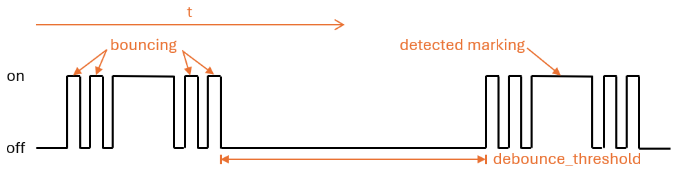
name : Calibration modeThe transition from unmarked to marked area and vice versa on the turntable can lead to a rapid back and forth jump ("bouncing") in the detection state of the sensor, which occurs particularly at slow rotation speeds and cannot be completely suppressed by the calibration. This bouncing of the state leads to falsified measured values and to avoid this, the following settings can be applied.
The debounce threshold value debounce_threshold specifies the minimum time in milliseconds between falling and subsequent rising edge. The trigger from the sensor is only taken into account if the measured time between the two edges is above the configured value. This type of debouncing can be applied to both the variant using the digital as well as the analog input signal of the infrared sensor.
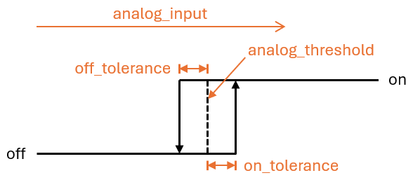
The two offset values off_tolerance and on_tolerance can be configured to use a hysteresis curve for the detection of the marked area on the turntable via the analog signal. This compensates the jitter of the analog signal and thus minimizes any possible bouncing of the detection status for the marked area on the turntable. This type of debouncing only works when using the analog input signal of the infrared sensor.
By carefully configuring the update interval update_interval and the number of samples per update ( samples ) for the analog sensor analog_input , the curve of the analog signal can be smoothed to such an extent that short-term fluctuations are eliminated. However, bear in mind that excessive update intervals can lead to individual rotations no longer being detected at very high rotation speeds, as the time between the rising and subsequent falling edge is then shorter than the set update interval. Also this type of debouncing only works when using the analog input signal of the infrared sensor.
To synchronize the meter reading in the Ferraris component with the actual meter reading of the Ferraris electricity meter, the value of the energy meter sensor can be explicitly overwritten. The two actions ferraris.set_energy_meter and ferraris.set_rotation_counter (see Actions) are provided for this purpose.
ヒント
Usually, you need to use only one of the two actions, depending on whether you want to set the meter reading in kilowatt hours or in number of rotations.
The actions can be used in different ways, depending on whether the energy meter reading is to be set manually via the user interface or trigger-based via automations and scripts. Two possible usage examples are described below, but there are more possibilities existing which are not described here.
For instance, the following configuration steps are carried out (in this example to overwrite the energy meter with a kilowatt hours value):
 number :
  - platform : template
    id : target_energy_value
    name : Manual meter reading
    icon : mdi:counter
    unit_of_measurement : kWh
    device_class : energy
    entity_category : config
    mode : box
    optimistic : true
    min_value : 0
    max_value : 1000000
step : 0.01 button :
- platform : template
name : Overwrite meter reading
icon : mdi:download
entity_category : config
on_press :
- ferraris.set_energy_meter :
id : ferraris_meter
value : !lambda |-
float val = id(target_energy_value).state;
return (val >= 0) ? val : 0; For instance, the following configuration steps are carried out:
ferraris.set_energy_meter is used). api :
# ...
actions :
- action : set_energy_meter
variables :
target_value : float
then :
- ferraris.set_energy_meter :
id : ferraris_meter
value : !lambda |-
return (target_value >= 0)
? target_value
: 0;- id : ' 1234567890 '
alias : Reset energy meter reading
trigger :
- platform : time
at : 00:00:00
condition :
- condition : template
value_template : ' {{ now().day == 1 }} '
action :
- action : esphome.ferraris_meter_set_energy_meter
data :
target_value : 0
mode : singleIn order not to reduce the service life of the flash memory on the ESP microcontroller, the Ferraris component does not store any data persistently in the flash. As a result, it cannot remember the meter reading after a restart of the microcontroller and the meter starts counting at 0 kWh with every boot process. Therefore, the meter reading would have to be overwritten manually with a value read from the Ferraris electricity meter after each restart. As this is not very user-friendly, there is the option of persisting the last meter reading in Home Assistant and transferring it to the microcontroller when booting.
For this to work, the following configuration steps must be carried out:
input_number.electricity_meter_last_value ). number :
- platform : homeassistant
id : last_energy_value
entity_id : input_number.electricity_meter_last_valueenergy_start_value refers to the number component created under 2. ferraris :
# ...
energy_start_value : last_energy_value- id : ' 1234567890 '
alias : Update meter reading cache
trigger :
- platform : state
entity_id :
- sensor.ferraris_meter_energy
condition : []
action :
- action : input_number.set_value
target :
entity_id : input_number.electricity_meter_last_value
data :
value : ' {{ states(trigger.entity_id) }} '
mode : singleenergy_meter in the YAML configuration file which updates the number component created under 2 directly from ESPHome. However, this leads to a longer processing time per rotation in the microcontroller and may result in individual rotations of the turntable not being detected in the event of very high power consumption (and hence, very high rotation speeds). Therefore, I recommend the variant with the automation in Home Assistant.

