esphome ferraris meter
Release 1.4.1
메모
영어 버전의 경우 독일어 버전입니다. 아래로 스크롤하거나 여기를 클릭하십시오.
Ferraris Meter는 ESP 펌웨어를 생성하기위한 에스피드 구성 요소로, ESP 마이크로 컨트롤러 및 적외선 센서를 사용하여 아날로그 페라리 스 스트림 미터의 턴테이블의 속도와 회전을 결정할 수 있으며, 이로부터 현재 전력 소비 및 미터 상태를 계산할 수 있습니다. 그런 다음이 값은 추가 처리를 위해 Home Assistant와 같은 홈 자동화 소프트웨어로 전송 될 수 있습니다.
소프트웨어 (하드웨어 샘플 구조가 포함 된 문서 포함)는 기본적으로 시장 접근, 특정 목적에 대한 적합성 및 타사 권리의 비 침입을 포함하되 이에 국한되지 않는 특급 또는 암묵적 보증없이 기본적으로 제공됩니다. 저자 또는 저작권 소유자는 계약 또는 책임 소송에서 소프트웨어 또는 사용 또는 소프트웨어와 관련된 기타 상점과 관련하여 발생하는 계약 또는 책임 소송, 무단 행위 또는 기타 기타에 관계없이 청구, 손해 또는 기타 의무에 대해 책임을지지 않습니다.
ESP 마이크로 컨트롤러 (예 : 전압 공급을 포함한 ESP8266 또는 ESP32) 및 적외선 센서 (예 : TCRT5000) 만 필요합니다. 페라리 미터의 순수한 기능의 경우, ESP8266은 마이크로 컨트롤러로서 충분하다. 적외선 센서의 경우 3.3V-5V 입력 전압을 갖춘 완성 된 TCRT5000 기반 브레이크 아웃 모듈이 있으며, 이는 디지털 출력을 보정 할 수있는 제어 가능한 저항 (전위차계)이 있습니다. 이 TCRT5000 모듈에는 센서 칩의 전원 공급 장치 용 4 핀 -VCC 및 GND와 디지털 출력 D0 및 아날로그 출력 A0이 있습니다.
페라리 전류 미터의 커버 플레이트에 센서를 배치 할 때 약간의 기술과 정밀 작업이 필요합니다. 적외선 송신기/수용자 센서의 수용자 커플은 턴테이블 위에 밀리미터의 중간에 정렬되어 턴테이블을 똑바로 가리 킵니다.
원칙적으로 페라리 미터 구성 요소는 다음과 같은 개발 변형을 지원합니다.
Esphome 펌웨어를 만들려면 Yaml 기반 구성 파일을 작성해야합니다. 이 저장소에 제공된 샘플 구성 파일 중 하나를 시작점으로 사용하여 필요에 맞게 조정할 수 있습니다.
원칙적으로 에스피 펌웨어를 구축하는 두 가지 방법이 있습니다.
선택해야 할 메소드는 Esphome에 대한 신뢰와 그래픽 사용자 인터페이스 또는 명령 줄에서 작업하는 것을 선호하는지 여부에 따라 다릅니다. 또한 펌웨어를 구축하는 호스트의 성능은 프로세스를 가속화하는 역할을 할 수 있습니다.
메모
이 저장소 ( "Forken")를 복사하고 복사 된 저장소의 샘플 구성에 적응할 필요는 없습니다 . 대신, 샘플 구성을 저장하고 조정하거나 홈 어시스턴트 호스트에서 적응 된 구성을 제거하기에 충분합니다 (Esphome Device Compiler Add-On을 사용하여 Esphome 펌웨어 생성이 필요한 경우).
다음 섹션에서는 펌웨어 구성 파일에 포함 된 가장 중요한 구성 요소를 설명합니다.
구성 요소 페라리는 필수적이며 센서를 사용하려면 추가해야합니다.
Esphome의 일부가 아닌 사용자 지정 구성 요소이므로 명시 적으로 가져와야합니다. 가장 쉬운 방법은이 저장소에서 직접 구성 요소를로드하는 것입니다.
 external_components :
  - source : github://jensrossbach/esphome-ferraris-meter
    components : [ferraris]
팁
위의 예에서, 구성 요소의 최신 상태는 Repositorie의 main 지점에서 초대됩니다. 그러나 버전 번호를 통해 릴리스 스탠드를 참조하여 사용되는 소프트웨어 스탠드를 더 많이 제어하고 "변경 사항을 깨기"에 더 잘 반응 할 수 있도록 권장합니다. 샘플 구성을 참조하여 수행 방법을 참조하십시오.
다음과 같은 일반 설정을 구성 할 수 있습니다.
| 옵션 | 유형 | 필요합니다 | 기준 | 설명 |
|---|---|---|---|---|
id | ID | 아니요 1 | - | 페라리스 구성 요소의 인스턴스 |
digital_input | 핀 | 예 2 | - | TCRT5000 모듈의 디지털 출력이 연결된 gpio 핀 |
analog_input | ID | 예 2 | - | TCRT5000 모듈의 아날로그 출력에 연결된 핀을 읽는 ADC 센서 |
analog_threshold | 번호 / ID 3 | 아니요 | 50 | 아날로그 입력을 통한 혁명 감지를위한 임계 값 |
off_tolerance | 번호 / ID 3 | 아니요 | 0 | 떨어지는 측면에 대한 아날로그 임계 값에 대한 음의 오프셋, 자세한 내용은 Section Section을 참조하십시오. |
on_tolerance | 번호 / ID 3 | 아니요 | 0 | 상승 측면에 대한 아날로그 임계 값에 대한 양의 오프셋, 자세한 내용은 Section Depressing을 참조하십시오. |
rotations_per_kwh | 숫자 | 아니요 | 75 | kWh 당 턴테이블의 혁명 수 (값은 페라리스 전류 미터에 나타납니다) |
debounce_threshold | 번호 / ID 3 | 아니요 | 400 | 혁명이 고려되도록 떨어지는 측면과 후속 증가 사이의 밀리 초 사이의 최소 시간, 자세한 내용은 Section Destrolling을 참조하십시오. |
energy_start_value | ID | 아니요 | - | 소비량 미터의 시작 값으로 부팅에 값을 사용하는 숫자 구성 요소 |
1 특정 응용 프로그램에는 구성 요소 id 필요합니다.
2 하드웨어 개발 변형에 따라 두 가지 구성 요소 중 하나 인 digital_input 또는 analog_input 이 필요합니다.
3 구성 요소 analog_threshold , off_tolerance , on_tolerance 및 debounce_threshold 는 고정 번호 또는 숫자 구성 요소의 ID를 기대합니다. 후자는 사용자 인터페이스 (예 : 템플릿 번호 구성 요소를 사용하여)를 통해 값을 구성 할 수 있습니다.
 ferraris :
  id : ferraris_meter
  digital_input : GPIO4
  rotations_per_kwh : 75
  debounce_threshold : 400
energy_start_value : last_energy_valueESP를 홈 비서에 통합하려면 API 구성 요소가 필요합니다. 대체 홈 자동화 소프트웨어를 사용하는 경우 대신 MQTT 구성 요소를 추가해야합니다. 그러나 미터 스탠드를 덮어 쓰기 또는 재시작 후 마지막 미터 스케일의 복원과 같은 특정 메커니즘 (자세한 내용은 아래 참조) 및 더 이상 작동하지 않습니다.
아래는 Home Assistant (및 암호화 된 API)와의 통합의 예입니다.
 api :
  encryption :
    key : !secret ha_api_key
다음은 MQTT를 사용하는 대체 홈 자동화 소프트웨어와 함께 사용되는 예입니다.
 mqtt :
  broker : 10.0.0.2
  username : !secret mqtt_user
  password : !secret mqtt_password
Wi -Fi 구성 요소를 사용할 수 있어야합니다. 그렇지 않으면 센서 값을 다른 장치로 쉽게 전송할 수 없습니다.
 wifi :
  ssid : !secret wifi_ssid
password : !secret wifi_password페라리 스 성분에는 계산 된 소비 값과 교정 모드를위한 진단 센서를 출력하는 1 차 센서가 있습니다. 모든 센서는 선택 사항이며 필요하지 않은 경우 제외 될 수 있습니다.
다음 1 차 센서를 구성 할 수 있습니다.
| 감지기 | 유형 | 장치 클래스 | 주 수업 | 단위 | 설명 |
|---|---|---|---|---|---|
power_consumption | 수치 | power | measurement | w | 현재 전력 소비 |
energy_meter | 수치 | energy | total_increasing | 와트시 | 총 전류 소비 (전기 미터/미터 상태) |
Esphome 센서 구성 요소의 문서에서 개별 요소의 구성 옵션에 대한 자세한 정보를 찾을 수 있습니다.
 sensor :
  - platform : ferraris
    power_consumption :
      name : Momentanverbrauch
    energy_meter :
name : Verbrauchszähler 다음 진단 센서를 구성 할 수 있습니다.
| 감지기 | 유형 | 설명 |
|---|---|---|
rotation_indicator | 이진 | 턴테이블의 표시가 적외선 센서 앞에 있는지 여부를 보여줍니다 (교정 모드에서만 작동 함) |
Esphome 이진 센서 구성 요소의 문서에서 개별 요소의 구성 옵션에 대한 자세한 정보를 찾을 수 있습니다.
 binary_sensor :
  - platform : ferraris
    rotation_indicator :
name : Umdrehungsindikator 진단 목적으로 페라리 스 성분에는 스위치가 있습니다. 여기에는 이름 calibration_mode 가 있으며 구성 요소를 교정 모드에 넣는 데 사용할 수 있습니다 (자세한 내용은 섹션 교정 참조).
 switch :
  - platform : ferraris
    calibration_mode :
name : Kalibrierungsmodus페라리스 구성 요소는 미터 스케일을 설정하고 전환 카운터를 설정하기위한 두 가지 동작을 제공합니다.
| 행동 | 설명 |
|---|---|
ferraris.set_energy_meter | 지정된 값에 미터 상태를 배치합니다 |
| 매개 변수 | 유형 | 영역 | 설명 |
|---|---|---|---|
value | float | > = 0 | 킬로와트 시간 (KWH)의 미터 상태의 목표 값 |
메모
현재 미터 상태의 센서에는 유닛 WH (Watt Hours) 가 있지만 미터 스탠드를 덮어 쓰는 동작은 유닛 KWh (킬로와트 시간)를 사용하지만 아날로그 페라리 전류 미터는 일반적으로 미터를 표시하기 때문입니다.
| 행동 | 설명 |
|---|---|
ferraris.set_rotation_counter | 지정된 값에 회전 카운터를 배치합니다 |
메모
페라리스 구성 요소가 와트 시간이나 킬로와트 시간이 아닌 혁명과 내부적으로 작동하기 때문에 미터 스탠드를 설정하는 조치는 회전 카운터도 간접적으로 설정합니다.
| 매개 변수 | 유형 | 영역 | 설명 |
|---|---|---|---|
value | uint64 | > = 0 | 숫자 회전의 회전 카운터의 목표 값 |
이 섹션에서는 페라리스 구성 요소에 대한 다양한 응용 프로그램 예가 설명되어 있습니다.
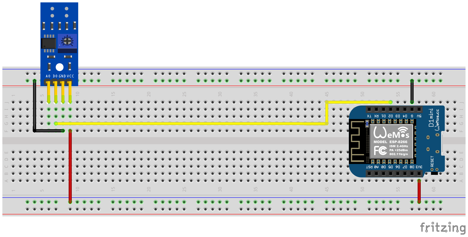
이 변형에서, 적외선 센서의 디지털 출력은 턴테이블의 회전을 식별하는 데 사용됩니다. 아날로그 출력은 필요하지 않으며, 다른 핀은 마이크로 컨트롤러의 해당 핀에 연결되어야합니다. VCC의 경우 ESPS의 3.3V 출력을 사용해야하고 디지털 출력 D0은 무료 GPIO 핀에 연결되어야합니다 (예 : GPIO4, D1 미니의 핀 D2에 해당).
다음 플러그인 회로 다이어그램은 ESP8266 D1 미니 개발 보드가 마이크로 컨트롤러로서 실험 설정의 예를 보여줍니다.
드라이버의 도움을 받으면 전위차계를 통해 디지털 출력 신호를 보정해야합니다. 센서 뒷면에있는 두 개의 녹색 LED가 도움이됩니다. 센서에 전기가 공급되면 오른쪽 LED가 영구적으로 빛납니다. 왼쪽 LED는 "장애물"이 인식되지 않은 한 빛나고 반사가 중단되었을 때 만료됩니다. 후자는 페라리 전류 미터의 턴테이블의 표시가 센서 앞에서 방황하는 조건입니다. 따라서 전위차계는 마커가 앞쪽으로 밀려 나가 자마자 마킹이 적외선 발신자/수신자 부부의 영역에 없을 때 왼쪽 LED가 여전히 빛나도록 설정해야합니다. 이것은 매우 작은 영역 일 뿐이며이 설정을 찾기가 조금 어려울 수 있습니다. 이 프로세스에 대한 추가 지원을 보려면 페라리 미터 펌웨어에서 교정 모드를 활성화 할 수 있습니다. 자세한 내용은 교정 섹션을 참조하십시오.
팁
전위차계에 적합하고 기능적인 설정을 찾을 수없는 경우 적외선 센서의 아날로그 출력을 대안으로 사용할 수 있습니다 (다음 섹션을 참조하십시오.
TCRT5000 모듈의 디지털 출력에 연결된 PIN YAML 구성 파일의 Ferraris 구성 요소에 대해 소프트웨어 측면을 구성해야합니다.
 ferraris :
  id : ferraris_meter
  digital_input : GPIO4
  # ...
예제 구성 : ferraris_meter_digital.yaml
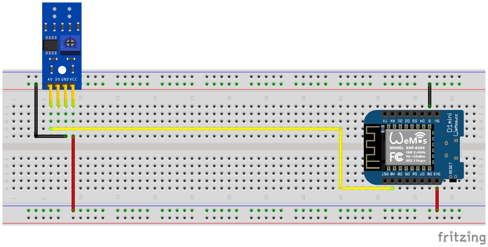
이 변형에서, 적외선 센서의 아날로그 출력은 턴테이블의 회전을 식별하는 데 사용됩니다. 디지털 출력이 필요하지 않으며 다른 핀은 마이크로 컨트롤러의 해당 핀에 연결되어야합니다. VCC의 경우 ESPS의 3.3V 출력을 사용하고 아날로그 출력 A0은 자유 ADC 핀에 연결되어야합니다 (예 : GPIO17, D1 미니의 핀 A0에 해당).
다음 플러그인 회로 다이어그램은 ESP8266 D1 미니 개발 보드가 마이크로 컨트롤러로서 실험 설정의 예를 보여줍니다.
TCRT5000 모듈의 전위차계를 통한 교정은 더 이상 필요하지 않습니다. 대신 소프트웨어 측은 아날로그 입력에 대해 구성되어야하며 선택적으로 히스테리시스 특성에 대한 오프셋 값을 구성해야합니다 (아래의 저하 섹션 참조). 여기서 페라리 스 성분의 교정 모드도 도움이 될 수 있습니다. 자세한 내용은 교정 섹션을 참조하십시오.
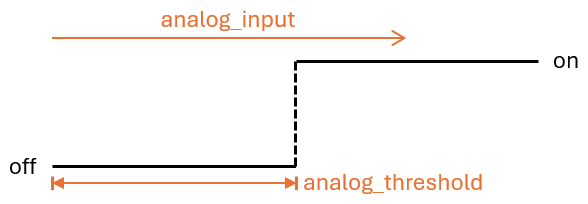
임계 값 analog_threshold 아날로그 신호가 "인식 된"(턴테이블의 표시 영역)로 취급되고 "인식되지 않은"(턴테이블의 표시되지 않은 영역)로 취급 될 때 제어합니다. ADC 센서의 값이 임계 analog_input 보다 크면 마킹이 인식되는 것으로 간주되며, 더 작거나 동일하며 인식되지 않습니다.
예를 들어 소프트웨어 측면과 같은 다음 구성 단계를 수행해야합니다.
 sensor :
  - platform : adc
    id : adc_input
    pin : GPIO17
    internal : true
    raw : true
    samples : 10
update_interval : 50ms number :
- platform : template
id : adc_threshold
name : ADC Schwellwert
icon : mdi:speedometer-slow
entity_category : config
mode : box
optimistic : true
initial_value : 50
min_value : 0
max_value : 1000
step : 1analog_threshold analog_input . ferraris :
id : ferraris_meter
analog_input : adc_input
analog_threshold : adc_threshold
# ...analog_threshold 의 고정 수치 값을 지정할 수도 있습니다. 이 경우 2 단계를 생략 할 수 있습니다. ferraris :
# ...
analog_threshold : 45
# ... 오프셋 값 off_tolerance 및 on_tolerance 의 구성은 analog_threshold 구성과 매우 유사하므로 위의 예에서 명시 적으로 표시되지 않았습니다.
예제 구성 : ferraris_meter_analog.yaml
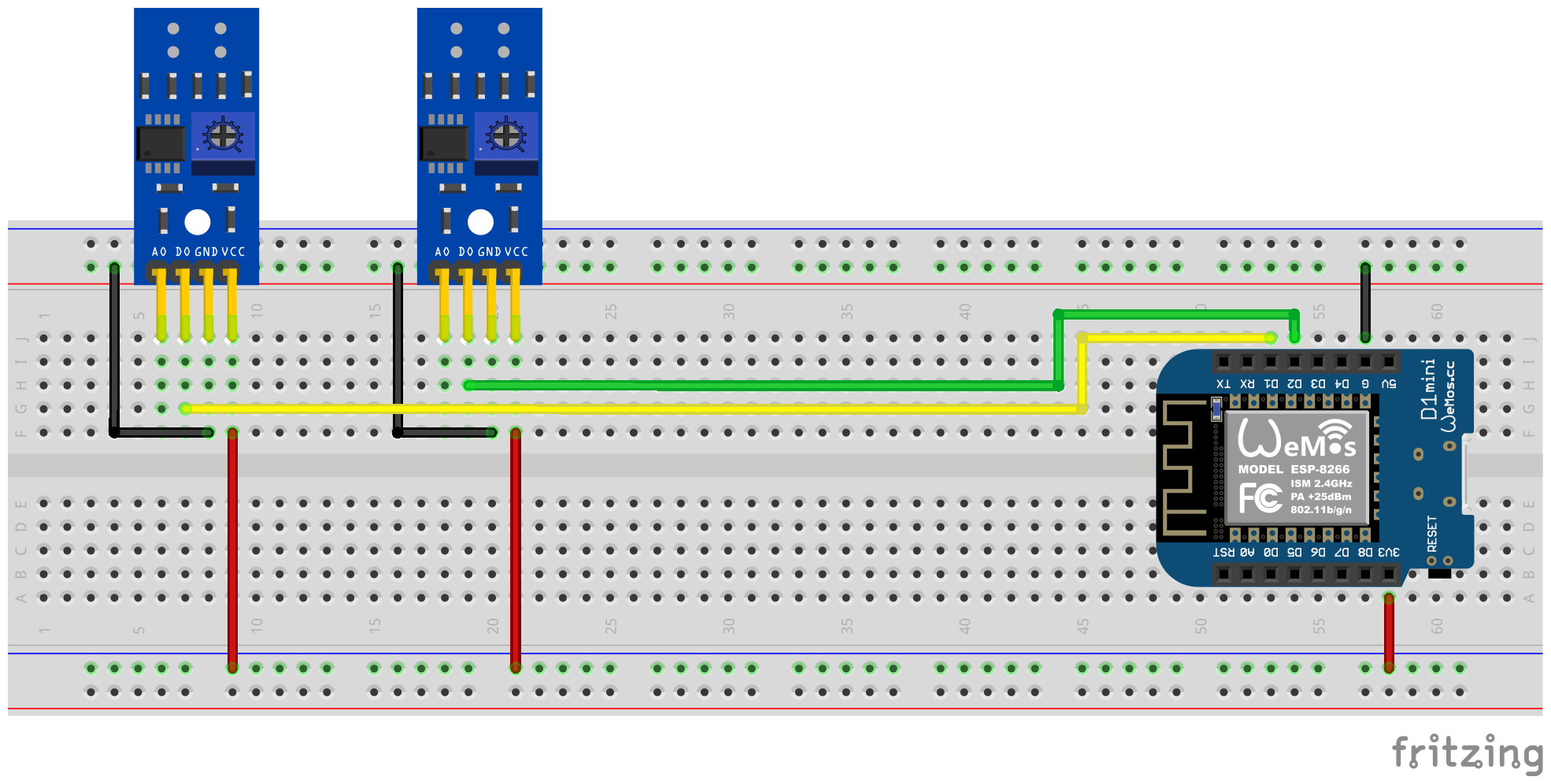
단일 ESP 마이크로 컨트롤러로 둘 이상의 페라리 전류 카운터를 읽을 수도 있습니다. 이를 위해서는 마이크로 컨트롤러에 추가적인 적외선 센서 / TCRT5000 모듈과 추가 무료 GPIO 핀이 필요합니다. 이미 설명 된 바와 같이, TCRT5000 모듈은 VCC 및 GND를 통해 ESP 마이크로 컨트롤러의 전압 소스에 연결되며 D0 출력은 각각 무료 GPIO 핀으로 ESP 보드에 연결됩니다.
메모
이론적으로, 변형은 적외선 센서의 아날로그 출력과 함께 사용될 수 있지만 ESP 마이크로 컨트롤러의 ADC 가능 핀은 순수한 디지털 핀보다 더 제한적입니다. 특히, 하나의 ADC 만있는 ESP8266은 아날로그 출력을 통해 여러 적외선 센서를지지하는 데 부적합합니다.
다음 플러그인 회로 다이어그램은 ESP8266 D1 Mini에 연결된 2 개의 TCRT5,000 모듈이있는 테스트 설정의 예를 보여줍니다.
그러나 각 추가적인 적외선 센서는 마이크로 컨트롤러의 하중을 증가시키고, 특히 턴테이블의 매우 빠른 속도에서 하드웨어는 한계에 더 가깝습니다.
예를 들어 소프트웨어 측면과 같은 다음 구성 단계를 수행해야합니다.
 ferraris :
  - id : ferraris_meter_1
    digital_input : GPIO4
    # ...
  - id : ferraris_meter_2
    digital_input : GPIO5
# ...ferraris_id 항목을 통해 Ferraris 구성 요소의 해당 인스턴스를 곱하고 할당해야합니다. sensor :
- platform : ferraris
ferraris_id : ferraris_meter_1
power_consumption :
name : Momentanverbrauch 1
energy_meter :
name : Verbrauchszähler 1
- platform : ferraris
ferraris_id : ferraris_meter_2
power_consumption :
name : Momentanverbrauch 2
energy_meter :
name : Verbrauchszähler 2
binary_sensor :
- platform : ferraris
ferraris_id : ferraris_meter_1
rotation_indicator :
name : Umdrehungsindikator 1
- platform : ferraris
ferraris_id : ferraris_meter_2
rotation_indicator :
name : Umdrehungsindikator 2
switch :
- platform : ferraris
ferraris_id : ferraris_meter_1
calibration_mode :
name : Kalibrierungsmodus 1
- platform : ferraris
ferraris_id : ferraris_meter_2
calibration_mode :
name : Kalibrierungsmodus 2예제 구성 : ferraris_meter_multi.yaml
전위차계 또는 아날로그 임계 값의 조정뿐만 아니라 적외선 센서의 위치 및 정렬 동안, 센서 조건의 변화는 턴테이블에 대한 표시의 실제 감지에 해당하지 않기 때문에 페라리스 전류 미터의 턴테이블의 회전을 측정하는 것은 거의 의미가 없습니다. 따라서 교정 모드를 위해 스위치를 켜면 페라리스 구성 요소를 교정 모드에 넣을 수 있습니다 (액추에이터 참조). 교정 모드가 활성화되는 한 소비 데이터의 계산이 수행되지 않으며 해당 센서 (기본 센서 참조)는 변경되지 않습니다. 대신, 회전 표시를위한 진단 센서 (진단 센서 참조)가 활성화되어 올바른 정렬을 지원하는 데 사용될 수도 있습니다. 센서는 마크가 턴테이블에서 인식되었을 때 on 에 있으며 마킹이 인식되지 않은 경우 off .
교정 모드를 사용할 수 있으려면 calibration_mode 및 rotation_indicator 가 YAML 파일로 구성되어야합니다.
 binary_sensor :
  - platform : ferraris
    rotation_indicator :
      name : Umdrehungsindikator

switch :
  - platform : ferraris
    calibration_mode :
name : Kalibrierungsmodus턴테이블에서 표시되지 않은 영역으로 및 그 반대의 전환은 센서 식별 상태의 빠른 앞뒤로 ( "튀는")로 이어질 수 있으며, 이는 특히 느린 회전 속도에서 발생하며 교정에 의해 완전히 억제 될 수 없습니다. 이 타박상은 위조 된 측정으로 이어지고 피하기 위해 다음과 같은 설정이 있습니다.
debounce_threshold Depressing 임계 값은 낙하와 후속 증가 측면 사이의 밀리 초의 최소 시간을 지정합니다. 측정 된 시간이 구성된 두 측면 사이에있는 경우에만 구성된 값은 센서 트리거입니다. 이 유형의 우울증은 적외선 센서의 디지털 및 아날로그 입력 신호를 모두 사용할 때 작동합니다.
off_tolerance 및 on_tolerance 의 두 오프셋 값은 아날로그 신호를 통해 턴테이블에서 표시된 영역을 감지하기 위해 히스테리시스 특성을 사용하도록 구성 될 수 있습니다. 이것은 아날로그 신호의 "떨림"을 보상하고 턴테이블의 표시된 영역에 대한 식별 상태의 가능한 멍이 최소화됩니다. 이 유형의 우울증은 적외선 센서의 아날로그 입력 신호를 사용할 때만 작동합니다.
업데이트 간격의 영리한 구성 update_interval 과 아날로그 센서 아날로그 analog_input 의 업데이트 당 샘플링 수 ( samples )를 사용하면 아날로그 신호의 곡선이 스무딩되어 단기 변동이 제거 될 수 있습니다. 그러나 업데이트 간격이 너무 커지면 개별 혁명이 더 이상 매우 높은 회전 속도로 인식되지 않는다는 사실을 염두에 두어야합니다. 이 유형의 우울증은 적외선 센서의 아날로그 입력 신호를 사용할 때만 작동합니다.
페라리스 전류 미터의 실제 미터와 페라리 스 성분의 미터 상태를 보상하기 위해 소비량 미터 센서의 값을 명시 적으로 덮어 쓸 수 있습니다. 이를 위해 두 ferraris.set_energy_meter 및 ferraris.set_rotation_counter .
팁
일반적으로 킬로와트 시간 또는 혁명 수에 미터를 배치할지 여부에 따라 두 가지 조치 중 하나만 필요합니다.
사용자 인터페이스에 의해 미터 레벨의 설정을 처리 해야하는지 또는 자동화 및 스크립트를 통해 자동으로 처리 해야하는지 여부에 따라 동작은 다양한 방식으로 사용할 수 있습니다. 두 가지 가능한 적용 예제는 아래에 설명되어 있지만 여기에는 설명되지 않은 다른 옵션이 있습니다.
예를 들어, 다음 구성 단계가 수행됩니다 (이 예에서 미터 스탠드를 킬로와트 시간 값으로 설정하기 위해).
 number :
  - platform : template
    id : target_energy_value
    name : Manueller Zählerstand
    icon : mdi:counter
    unit_of_measurement : kWh
    device_class : energy
    entity_category : config
    mode : box
    optimistic : true
    min_value : 0
    max_value : 1000000
step : 0.01 button :
- platform : template
name : Verbrauchszähler überschreiben
icon : mdi:download
entity_category : config
on_press :
- ferraris.set_energy_meter :
id : ferraris_meter
value : !lambda |-
float val = id(target_energy_value).state;
return (val >= 0) ? val : 0; 예를 들어, 다음 구성 단계가 수행됩니다.
ferraris.set_energy_meter 캠페인)이 페라리 스션 조치 중 하나 인 사용자 정의 캠페인이 만들어집니다. api :
# ...
actions :
- action : set_energy_meter
variables :
target_value : float
then :
- ferraris.set_energy_meter :
id : ferraris_meter
value : !lambda |-
return (target_value >= 0)
? target_value
: 0;- id : ' 1234567890 '
alias : Zurücksetzen des Verbrauchszählers
trigger :
- platform : time
at : 00:00:00
condition :
- condition : template
value_template : ' {{ now().day == 1 }} '
action :
- action : esphome.ferraris_meter_set_energy_meter
data :
target_value : 0
mode : singleESP 마이크로 컨트롤러에서 플래시 메모리의 수명을 줄이지 않기 위해 페라리 스 성분은 플래시에 데이터를 지속적으로 저장하지 않습니다. 결과적으로, 마이크로 컨트롤러의 재시작으로 미터 상태를 먼저 기억할 수 없으며 카운터는 모든 보트에서 0kWh로 계산하기 시작합니다. 따라서 각 재시작 후에는 페라리 스케일 미터에 읽는 값으로 미터 스케일을 수동으로 덮어 써야합니다. 이것은 매우 사용자에게 친숙하지 않기 때문에 홈 어시스턴트의 마지막 미터 상태를 유지하고 마이크로 컨트롤러를 부팅 할 때이를 전송할 수 있습니다.
이 작업을 수행하려면 다음 구성 단계를 수행해야합니다.
input_number.stromzaehler_letzter_wert 와 함께이 예에서)에 생성됩니다. number :
- platform : homeassistant
id : last_energy_value
entity_id : input_number.stromzaehler_letzter_wertenergy_start_value 2 미만의 숫자 구성 요소를 나타냅니다. ferraris :
# ...
energy_start_value : last_energy_value- id : ' 1234567890 '
alias : Aktualisierung Verbrauchszähler-Cache
trigger :
- platform : state
entity_id :
- sensor.ferraris_meter_verbrauchszaehler
condition : []
action :
- action : input_number.set_value
target :
entity_id : input_number.stromzaehler_letzter_wert
data :
value : ' {{ states(trigger.entity_id) }} '
mode : singleenergy_meter 에 대한 센서 자동화도 생성 될 수 있습니다. 그러나 숫자 구성 요소는 2 세 미만의 숫자 구성 요소를 업데이트 할 수 있습니다. 그러나 마이크로 컨트롤러의 혁명 당 처리 시간이 연장되어 전력 소비가 매우 높기 때문에 턴테이블의 개별 라운드가 기록되지 않을 수 있습니다 (따라서 매우 높은 회전 속도). 따라서 홈 어시스턴트의 자동화와 함께 변형을 권장합니다.Ferraris Meter는 ESP 마이크로 컨트롤러와 적외선 센서를 사용하는 ESP 펌웨어를 생성하기위한 에스피드 구성 요소입니다. 아날로그 페라리 전기 미터의 회전 수와 체조의 속도를 계산하고 현재의 전기 소비 및 미터 판독기를 계산합니다. 그런 다음 논문 값은 추가 처리를 위해 홈 조수로 홈 자동화 소프트웨어 검색으로 보낼 수 있습니다.
소프트웨어 (예제 하드웨어 설정을 포함한 문서 포함)는 상품, 특정 목적에 대한 적합성 및 비 연방 보증을 포함하여 명시 적 또는 묵시적 보증없이 "그대로"제공됩니다. 어떠한 경우에도 저자 또는 저작권 보유자는 계약, 불법 행위 또는 기타, 소프트웨어의 사용 또는 사용 또는 기타 거래에 관계없이 청구, 손해 또는 기타 책임에 대해 거짓말을해서는 안됩니다.
하드웨어 측면에서는 ESP 마이크로 컨트롤러 (예 : ESP8266 또는 ESP32, 전원 공급 장치)와 적외선 센서 (예 : TCRT5000) 만 요청됩니다. ESP8266 마이크로 컨트롤러는 페라리 미터의 순수한 기능으로 완전히 가득 차 있습니다. 적외선 센서의 경우 3.3V-5V 입력 전압을 갖춘 기성품 TCRT5000 기반 브레이크 아웃 모듈이 있으며, 따라서 센서의 디지털 출력을 보정하기위한 조정 가능한 저항 (전위차계)이 있습니다. 논문 TCRT5000 모듈에는 센서 칩의 전원 공급 장치 용 VCC 및 GND와 디지털 출력 D0 및 아날로그 출력 A0이 있습니다.
페라리 전기 미터의 커버 플레이트에 센서를 배치하려면 약간의 기술과 정밀 작업이 필요합니다. 센서의 적외선 송신기/수신기 쌍은 밀리미터 정밀도로 턴테이블 위로 중앙에 정렬되어야하며 턴테이블에 직선을 가리 킵니다.
페라리 미터 구성 요소는 기본적으로 다음 설정 변형을 지원합니다.
에스피드 펌웨어를 만들려면 YAML 기반 구성 파일을 생성해야합니다. 이 저장소에서 입증 된 예제 구성 파일 중 하나를 시작점으로 사용하여 필요에 맞게 조정할 수 있습니다.
원칙적으로 에스피 펌웨어를 구축하는 두 가지 방법이 있습니다.
어떤 방법을 선택 해야하는지는 Esphome에 익숙한 지, 그래픽 사용자 인터페이스 또는 명령 줄을 선호하는지 여부에 따라 다릅니다. 또한 펌웨어를 구축하는 호스트의 성능은 프로세스 속도를 높이는 데 중요한 역할을 할 수 있습니다.
메모
이 저장소를 포크하고 포크 리포지토리 내부의 예제 구성에 적응할 필요는 없습니다 . 대신, 예제 구성을 로컬로 저장하고 적응 시키거나 홈 어시스턴트 호스트에 저장하는 것으로 충분합니다 (Esphome 장치 컴파일러 애드온으로 에스피 펌웨어를 구축하려는 경우).
다음 섹션에서는 펌웨어 구성 파일에 포함 된 가장 주목할만한 구성 요소를 설명합니다.
페라리스 구성 요소는 필수적이며 센서를 사용하려면 추가해야합니다.
이것은 Esphome의 일부가 아닌 사용자 정의 구성 요소이므로 명시 적으로 가져와야합니다. 가장 쉬운 방법은이 저장소에서 직접 구성 요소를로드하는 것입니다.
 external_components :
  - source : github://jensrossbach/esphome-ferraris-meter
    components : [ferraris]
팁
위의 예에서는 저장소의 main 브랜치의 최신 버전이로드됩니다. 그러나 어떤 소프트웨어 버전을 사용하고 "변경 사항을 깨기"에 더 잘 반응 할 수 있도록 릴리스 버전을 참조하기 위해 버전 번호를 사용하는 것이 좋습니다. 이 작업을 수행 할 수있는 방법에 대한 예제 구성을 참조하십시오.
다음과 같은 일반 구성 항목을 구성 할 수 있습니다.
| 옵션 | 유형 | 필수의 | 기본 | 설명 |
|---|---|---|---|---|
id | ID | 아니요 1 | - | 페라리스 구성 요소 인스턴스 |
digital_input | 핀 | 예 2 | - | TCRT5000 모듈의 디지털 출력이 연결된 gpio 핀 |
analog_input | ID | 예 2 | - | TCRT5000 모듈의 아날로그 출력에 연결된 핀을 읽는 ADC 센서 |
analog_threshold | 번호 / ID 3 | 아니요 | 50 | 아날로그 입력을 통한 회전 감지에 대한 임계 값 |
off_tolerance | 번호 / ID 3 | 아니요 | 0 | 하락 가장자리에 대한 아날로그 임계 값에 대한 음의 오프셋, 자세한 내용은 Decouncing 섹션을 참조하십시오. |
on_tolerance | 번호 / ID 3 | 아니요 | 0 | 상승 에지에 대한 아날로그 임계 값에 대한 양의 오프셋, 자세한 내용은 섹션 Decounging을 참조하십시오. |
rotations_per_kwh | 숫자 | 아니요 | 75 | KWH를 통한 턴테이블의 회전 수 (그 값은 일반적으로 페라리 전기 미터에 표시됩니다) |
debounce_threshold | 번호 / ID 3 | 아니요 | 400 | 최소한의 시간이 떨어지고 회전을 고려하기 위해 떨어지고 후속 상승 에지가 있습니다. |
energy_start_value | ID | 아니요 | - | 부팅 시간에 에너지 카운터의 시작 값으로 값을 사용하는 숫자 구성 요소 |
1 일부 사용 사례에는 구성 요소 id 필요합니다.
2 하드웨어 설정 변형에 따라 digital_input 또는 analog_input 중 하나만 요청합니다.
3 구성 요소 analog_threshold , off_tolerance , on_tolerance 및 debounce_threshold 는 숫자 구성 요소의 정적 번호 또는 ID를 기대합니다. 후자는 사용자 인터페이스 (예 : 템플릿 번호를 사용하여)를 통해 값의 구성을 허용합니다.
 ferraris :
  id : ferraris_meter
  digital_input : GPIO4
  rotations_per_kwh : 75
  debounce_threshold : 400
energy_start_value : last_energy_valueESP가 Home Assistant에 통합 된 경우 API 구성 요소가 필요합니다. 대체 홈 자동화 소프트웨어를 사용하는 경우 대신 MQTT 구성 요소를 추가해야합니다. 그러나 특정 메커니즘은 에너지 미터를 수동으로 덮어 쓰거나 다시 시작한 후 마지막 미터 판독 값을 복원하는 것으로 검색합니다 (자세한 내용은 아래의 레이크)는 더 이상 작동하지 않을 수 있습니다.
홈 비서 통합 (암호화 된 API 포함)에 대한 아래 예제를 참조하십시오.
 api :
  encryption :
    key : !secret ha_api_key
MQTT를 통한 대체 홈 자동화 소프트웨어를 사용하여 사용하기 위해 아래에서 아래에 있습니다.
 mqtt :
  broker : 10.0.0.2
  username : !secret mqtt_user
password : !secret mqtt_password그렇지 않으면 센서 값을 다른 컴퓨터로 쉽게 전송할 수 없으므로 WiFi 구성 요소가 있어야합니다.
 wifi :
  ssid : !secret wifi_ssid
password : !secret wifi_password페라리 스 성분은 계산 된 소비 값과 교정 모드를위한 진단 센서를 노출시키는 기본 센서를 제공합니다. 모든 센서는 선택 사항이며 필요하지 않은 경우 생략 할 수 있습니다.
다음 1 차 센서를 구성 할 수 있습니다.
| 감지기 | 유형 | 장치 클래스 | 주 수업 | 단위 | 설명 |
|---|---|---|---|---|---|
power_consumption | 숫자 | power | measurement | w | 현재 전력 소비 |
energy_meter | 숫자 | energy | total_increasing | 와트시 | 총 에너지 소비 (미터 읽기) |
각 항목의 자세한 구성 옵션은 Esphome 센서 구성 요소 구성을 참조하십시오.
 sensor :
  - platform : ferraris
    power_consumption :
      name : Power consumption
    energy_meter :
name : Meter reading 다음 진단 센서를 구성 할 수 있습니다.
| 감지기 | 유형 | 설명 |
|---|---|---|
rotation_indicator | 이진 | 턴테이블의 마크가 적외선 센서 앞에 있는지 여부를 나타냅니다 (교정 모드에서만 작동 함). |
For detailed configuration options of each item, please refer to ESPHome binary sensor component configuration.
 binary_sensor :
  - platform : ferraris
    rotation_indicator :
name : Rotation indicator For diagnostic purposes, the Ferraris component provides a switch with the name calibration_mode . It can be used to set the component to calibration mode (see section calibration for further information).
 switch :
  - platform : ferraris
    calibration_mode :
name : Calibration modeThe Ferraris component provides two actions for setting the energy meter reading and the rotation counter.
| 행동 | 설명 |
|---|---|
ferraris.set_energy_meter | Sets the energy meter reading to the provided value |
| 매개 변수 | 유형 | 범위 | 설명 |
|---|---|---|---|
value | float | >= 0 | Target value for the energy meter reading in kilowatt hours (kWh) |
메모
Although the sensor for the current meter reading has the unit Wh (watt hours) , the action for overwriting the meter reading has the unit kWh (kilowatt hours) , as the analog Ferraris electricity meters usually also display the meter reading in this unit.
| 행동 | 설명 |
|---|---|
ferraris.set_rotation_counter | Sets the rotation counter to the provided value |
메모
The action for setting the energy meter reading indirectly also sets the rotation counter as the Ferraris component internally works with rotations and not with watt hours or kilowatt hours.
| 매개 변수 | 유형 | 범위 | 설명 |
|---|---|---|---|
value | uint64 | >= 0 | Target value for the rotation counter in number of rotations |
This section describes various examples of usage for the Ferraris component.
In this variant, the digital output of the infrared sensor is used to detect rotations of the turntable. The analog output is not required, the other pins must be connected to the corresponding pins of the microcontroller. The 3.3V output of the ESP should be used for VCC and the digital output D0 must be connected to a free GPIO pin (eg GPIO4, corresponding to pin D2 on the D1 Mini).
The following breadboard schematic shows an example test setup using an ESP8266 D1 Mini development board as microcontroller.
The digital output signal of the infrared sensor must be calibrated via the potentiometer using a screwdriver; the two green LEDs on the back of the sensor help with this. The right-hand LED lights up continuously when the sensor is supplied with power. The left-hand LED lights up as long as no "obstacle" has been detected and goes out when the reflection has been interrupted. The latter is the state when the mark on the Ferraris electricity meter's turntable moves in front of the sensor. The adjustment of the potentiometer should therefore be set so that the left-hand LED just lights up when the marker is not in the range of the infrared transmitter/receiver pair and goes out as soon as the marker moves in front of it. This is only a very small range and it can be a little difficult to find this setting. To further assist with this process, the calibration mode can be enabled in the Ferraris Meter firmware, see section calibration for details.
Tip
In case you are unable to find an appropriate and working adjustment of the potentiometer, you can alternatively use the analog output of the infrared sensor, see next section.
On the software side, the pin which is connected to the digital output of the TCRT5000 module has to be configured for the Ferraris component in the YAML configuration file:
 ferraris :
  id : ferraris_meter
  digital_input : GPIO4
  # ...
Example configuration file: ferraris_meter_digital.yaml
In this variant, the analog output of the infrared sensor is used to detect rotations of the turntable. The digital output is not required, the other pins must be connected to the corresponding pins of the microcontroller. The 3.3V output of the ESP should be used for VCC and the analog output A0 must be connected to a free ADC pin (eg GPIO17, corresponding to pin A0 on the D1 Mini).
The following breadboard schematic shows an example test setup using an ESP8266 D1 Mini development board as microcontroller.
A calibration using the potentiometer on the TCRT5000 module is not needed. Instead, the threshold for the analog input and optionally the offset values for a hysteresis curve must be configured on the software side (see also section Debouncing further down). Here as well, the calibration mode of the Ferraris component could be helpful, see section calibration for details.
The threshold value analog_threshold controls when the analog signal is treated as "detected" (marked area of the turntable) and when it is treated as "not detected" (unmarked area of the turntable). If the value from the ADC sensor analog_input is greater than the threshold value, the marking is considered detected; if it is smaller than or equal to the threshold value, it is considered not detected.
On the software side, for instance, the following configuration steps must now be carried out:
 sensor :
  - platform : adc
    id : adc_input
    pin : GPIO17
    internal : true
    raw : true
    samples : 10
update_interval : 50ms number :
- platform : template
id : adc_threshold
name : ADC threshold
icon : mdi:speedometer-slow
entity_category : config
mode : box
optimistic : true
initial_value : 50
min_value : 0
max_value : 1000
step : 1analog_input refers to the ADC sensor created under 1. and the entry analog_threshold refers to the number component created under 2. ferraris :
id : ferraris_meter
analog_input : adc_input
analog_threshold : adc_threshold
# ...analog_threshold if the threshold value is already known and no longer needs to be configured/changed. In this case, step 2 can be omitted. ferraris :
# ...
analog_threshold : 45
# ... The configuration for the offset values off_tolerance and on_tolerance is very similar to the configuration of analog_threshold and therefore not explicitly shown in above example.
Example configuration file: ferraris_meter_analog.yaml
It is also possible to read more than one Ferraris electricity meter with a single ESP microcontroller. This requires multiple infrared sensors / TCRT5000 modules and additional free GPIO pins on the microcontroller. The TCRT5000 modules have to be connected to the voltage source of the ESP microcontroller via VCC and GND as described in the section Hardware Setup and the D0 outputs have to be connected to free GPIO pins on the ESP board.
메모
Theoretically, the variant with the analog output of the infrared sensor can also be used, but the ADC-capable pins on the ESP microcontrollers are stronger limited than the pure digital pins. Especially the ESP8266, which has a single ADC only, would therefore not be suitable to support multiple infrared sensors via their analog outputs.
The following breadboard schematic shows an example of an example test setup with two TCRT5000 modules connected to an ESP8266 D1 Mini.
However, bear in mind that each additional infrared sensor increases the load on the microcontroller and brings the hardware closer to its limits, especially with very high rotation speeds of the turntables.
On the software side, for instance, the following configuration steps must now be carried out:
 ferraris :
  - id : ferraris_meter_1
    digital_input : GPIO4
    # ...
  - id : ferraris_meter_2
    digital_input : GPIO5
# ...ferraris_id configuration entry. sensor :
- platform : ferraris
ferraris_id : ferraris_meter_1
power_consumption :
name : Power consumption 1
energy_meter :
name : Meter reading 1
- platform : ferraris
ferraris_id : ferraris_meter_2
power_consumption :
name : Power consumption 2
energy_meter :
name : Meter reading 2
binary_sensor :
- platform : ferraris
ferraris_id : ferraris_meter_1
rotation_indicator :
name : Rotation indicator 1
- platform : ferraris
ferraris_id : ferraris_meter_2
rotation_indicator :
name : Rotation indicator 2
switch :
- platform : ferraris
ferraris_id : ferraris_meter_1
calibration_mode :
name : Calibration mode 1
- platform : ferraris
ferraris_id : ferraris_meter_2
calibration_mode :
name : Calibration mode 2Example configuration file: ferraris_meter_multi.yaml
During the positioning and alignment of the infrared sensor as well as the adjustment of the potentiometer or the analog threshold, it makes little sense to measure the rotations of the Ferraris electricity meter's turntable and calculate the consumption values, as the changes in state of the sensor do not correspond to the actual detection of the mark on the turntable. It is therefore possible to set the Ferraris component to calibration mode by turning on the calibration mode switch (see Actors). As long as the calibration mode is activated, no calculation of the consumption data is performed and the corresponding sensors (see Primary Sensors) are not changed. Instead, the diagnostic sensor for the rotation indication (see Diagnostic Sensors) is active and can additionally be used to assist with correct alignment. The sensor has the on state when the marker on the turntable is detected and the off state when it is not detected.
To be able to use the calibration mode, the components calibration_mode and rotation_indicator must be configured in the YAML file:
 binary_sensor :
  - platform : ferraris
    rotation_indicator :
      name : Rotation indicator

switch :
  - platform : ferraris
    calibration_mode :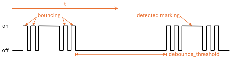
name : Calibration modeThe transition from unmarked to marked area and vice versa on the turntable can lead to a rapid back and forth jump ("bouncing") in the detection state of the sensor, which occurs particularly at slow rotation speeds and cannot be completely suppressed by the calibration. This bouncing of the state leads to falsified measured values and to avoid this, the following settings can be applied.
The debounce threshold value debounce_threshold specifies the minimum time in milliseconds between falling and subsequent rising edge. The trigger from the sensor is only taken into account if the measured time between the two edges is above the configured value. This type of debouncing can be applied to both the variant using the digital as well as the analog input signal of the infrared sensor.
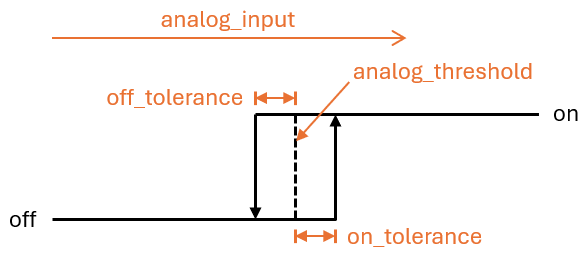
The two offset values off_tolerance and on_tolerance can be configured to use a hysteresis curve for the detection of the marked area on the turntable via the analog signal. This compensates the jitter of the analog signal and thus minimizes any possible bouncing of the detection status for the marked area on the turntable. This type of debouncing only works when using the analog input signal of the infrared sensor.
By carefully configuring the update interval update_interval and the number of samples per update ( samples ) for the analog sensor analog_input , the curve of the analog signal can be smoothed to such an extent that short-term fluctuations are eliminated. However, bear in mind that excessive update intervals can lead to individual rotations no longer being detected at very high rotation speeds, as the time between the rising and subsequent falling edge is then shorter than the set update interval. Also this type of debouncing only works when using the analog input signal of the infrared sensor.
To synchronize the meter reading in the Ferraris component with the actual meter reading of the Ferraris electricity meter, the value of the energy meter sensor can be explicitly overwritten. The two actions ferraris.set_energy_meter and ferraris.set_rotation_counter (see Actions) are provided for this purpose.
Tip
Usually, you need to use only one of the two actions, depending on whether you want to set the meter reading in kilowatt hours or in number of rotations.
The actions can be used in different ways, depending on whether the energy meter reading is to be set manually via the user interface or trigger-based via automations and scripts. Two possible usage examples are described below, but there are more possibilities existing which are not described here.
For instance, the following configuration steps are carried out (in this example to overwrite the energy meter with a kilowatt hours value):
 number :
  - platform : template
    id : target_energy_value
    name : Manual meter reading
    icon : mdi:counter
    unit_of_measurement : kWh
    device_class : energy
    entity_category : config
    mode : box
    optimistic : true
    min_value : 0
    max_value : 1000000
step : 0.01 button :
- platform : template
name : Overwrite meter reading
icon : mdi:download
entity_category : config
on_press :
- ferraris.set_energy_meter :
id : ferraris_meter
value : !lambda |-
float val = id(target_energy_value).state;
return (val >= 0) ? val : 0; For instance, the following configuration steps are carried out:
ferraris.set_energy_meter is used). api :
# ...
actions :
- action : set_energy_meter
variables :
target_value : float
then :
- ferraris.set_energy_meter :
id : ferraris_meter
value : !lambda |-
return (target_value >= 0)
? target_value
: 0;- id : ' 1234567890 '
alias : Reset energy meter reading
trigger :
- platform : time
at : 00:00:00
condition :
- condition : template
value_template : ' {{ now().day == 1 }} '
action :
- action : esphome.ferraris_meter_set_energy_meter
data :
target_value : 0
mode : singleIn order not to reduce the service life of the flash memory on the ESP microcontroller, the Ferraris component does not store any data persistently in the flash. As a result, it cannot remember the meter reading after a restart of the microcontroller and the meter starts counting at 0 kWh with every boot process. Therefore, the meter reading would have to be overwritten manually with a value read from the Ferraris electricity meter after each restart. As this is not very user-friendly, there is the option of persisting the last meter reading in Home Assistant and transferring it to the microcontroller when booting.
For this to work, the following configuration steps must be carried out:
input_number.electricity_meter_last_value ). number :
- platform : homeassistant
id : last_energy_value
entity_id : input_number.electricity_meter_last_valueenergy_start_value refers to the number component created under 2. ferraris :
# ...
energy_start_value : last_energy_value- id : ' 1234567890 '
alias : Update meter reading cache
trigger :
- platform : state
entity_id :
- sensor.ferraris_meter_energy
condition : []
action :
- action : input_number.set_value
target :
entity_id : input_number.electricity_meter_last_value
data :
value : ' {{ states(trigger.entity_id) }} '
mode : singleenergy_meter in the YAML configuration file which updates the number component created under 2 directly from ESPHome. However, this leads to a longer processing time per rotation in the microcontroller and may result in individual rotations of the turntable not being detected in the event of very high power consumption (and hence, very high rotation speeds). Therefore, I recommend the variant with the automation in Home Assistant.

