ch2i arduino boards
1.0.0
我的某些自定義板的Arduino核心具有迷你LORA,已通過Optiboot引導程序進行了優化,並具有不同的串行速度,以提高和改善上傳。這至少需要Arduino IDE v1.6.2,其中建議使用v1.8.6+。
另外,其中一些董事會在RFM95 LORA模塊中構建中,因此定義了常數引腳,因此編碼時您不會打擾您是連接的。請參閱部分預定的董事會
您的董事會應該已經閃爍了引導加載程序,而不是此存儲庫的範圍。這裡解釋了所有要燃燒引導加載程序
單擊右上角的“下載zip”按鈕。刪除zip文件,然後將提取的文件夾移至“ 〜/documents/arduino/hardware ”的位置。如果不存在,則創建“硬件”文件夾。
此文件夾應匹配您設置的一個文件夾中的一個文件夾,例如,在我的IDE中,在我的IDE中設置了sketchbook位置的設置為D:devtArduino ,所以我需要在D:devtArduinohardware中提取zip
提取後,您應該擁有諸如D:devtArduinohardwarech2i-arduino-boards-master類的東西,您當然可以將文件夾重命名為D:devtArduinohardwareCH2i
然後,打開Arduino IDE,並將出現在董事會菜單中的新類別。
好的,您已經下載並安裝了,準備上傳,但是如何開始?這是一個快速指南:
Mini Lora例如,如果您刷新引導程序optiboot_flash_atmega328p_250000_8MHZ.hex
一些帶有LORA RFM95模塊的板具有PIN定義,因此您可以在草圖中使用它。如果在Arduino IDE中選擇正確的板,則無需照顧值,只需使用定義的常數,例如LMIC堆棧
lmic_pinmap lmic_pins = {
    . nss = LORA_CS,
    . rxtx = LMIC_UNUSED_PIN,
    . rst = LORA_RESET,
    . dio = {LORA_DIO0, LORA_DIO1, LORA_DIO2},
};
另外,您可以在編譯時間檢查板使用(在Arduino IDE中選擇)
# if defined (AVR_MINILORA)
// Blah Blah
# elif defined (AVR_LORADUINO)
// Blah Blah
# elif defined (AVR_LORARADIONODE)
// Blah Blah
# else
# error "Unknown board selected"
# endif
這樣,您無需更改用於Lora Pinout的任何板的草圖。以下是針對每個板的銷釘定義
# define LED_BUILTIN 13
# define LED_RED     9
# define LED_GRN     6
# define LED_BLU     5
# define LED_PWM

# define BTN_ACTION 3

# define LORA_DIO0  2
# define LORA_DIO1  7
# define LORA_DIO2  8
# define LORA_RESET 9
# define LORA_CS    SS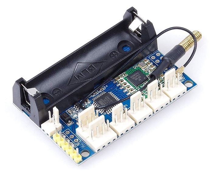
# define LED_BUILTIN 13
// Take care DIO pins are not connected to Digital Pin
// by default, you need to solder the one needed on connector
# define LORA_DIO0  2
# define LORA_DIO1  5
# define LORA_DIO2  6
# define LORA_DIO3  7
# define LORA_DIO5  8
# define LORA_RESET 9
# define LORA_CS    SS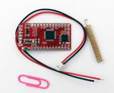
# define LED_BUILTIN 7
# define BAT_ANALOG A7
# define BTN_ACTION 5
# define FLASH_CS   8
# define LORA_DIO0  2
# define LORA_DIO1  4
# define LORA_RESET 9
# define LORA_CS    SS

