omega dca v1
1.0.0
DC adapter for the Omega Home Computer.
This is a simple DC adapter for the Omega Home Computer with the following features:
When I upgraded my Omega Home Computer with an audio amplifier board and a floppy drive I detected that, no matter how good was the power supply used, the Omega Home Computer suffered sudden resets due to power-related issues when performing some operations like, for example:
My Omega Home Computer was using the dc-adapter 1.6b from msxmakers! with an external 5V power supply.
I measured the peak power consumption of the Omega Home Computer at about 1.7A with the audio amplifier on and the floppy drive spinning.
I checked several +5V power supplies with no success:
I used an electronic load tester (DL24 150W) and a separate multimeter (VC99) to check the actual voltage of the power supplies under load (at the power supply connector end):
So according to those load tests and the observed peak power consumption, at least the 5V 8A power supply should be capable of powering the Omega Home Computer and its upgrades without issues. But it was not the case.
So I assumed the specific power demands of the audio amplifier and the floppy drive were causing the problems (undervoltage?) on the power rail of the Omega Home Computer. I decided to test if the problem went away by using a separate power supply for the audio amplifier/floppy and the Omega Home Computer. I connected two 5V power supplies with a common ground, one power supply to the Omega and the other to the audio amplifier board and floppy. And voilà, no more resets.
So in the end, I decided to design a small power adapter board to provide separate power circuits to the Omega Home Computer, the audio amplifier and video converter, and the floppy drive, and while at it, added several protections just in case something went wrong with the components.
As there are lots of cheap ready to use mini boards providing part of the requirements needed, I just built a "franken-board" cannibalizing other boards to achieve the final goal. The Omega DC Adapter was born.
The Omega DC Adapter is a small power adapter board to provide protected and regulated power to the Omega Home Computer. It supports the connection of an external DC power supply and a power switch to control power to the computer.

The Omega DC Adapter provides 3 independent power circuits:
The Omega DC Adapter PCB is a 2-layer design that glues a bunch of ready-to-use mini boards:
There are aswell:
The mini boards are soldered directly to the Omega DC Adapter PCB using pin headers.

Power circuits #2 and #3 can be merged if desired by populating only J5 and U3 (or J3 and U4) and closing the jumper JP3. Otherwise, jumper JP3 should always be open.
It is recommended to always test all the boards before assembling them to verify that they behave as per their specifications.
This board provides the reverse polarity protection for the Omega DC Adapter and is based on the 4435 P-MOSFET.
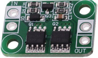
It can work up to 30V 4A and adds minimal voltage drop due to its very low RDS(on) of 20mOhm. The board works at the external power supply voltage, which must be between +6.5V and +24V as per the Omega DC Adapter design specifications, thus the voltage drop is unimportant in this case.
The mini step-down boards are based on the MP2315 high efficient synchronous step down switch mode converter.
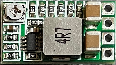
This integrated circuit provides thermal shutdown at 150C and has a per-cycle current limit protection, which limits current to a 5.5A typically. The mini step-down board supports input voltages from 4.5V to 24V, but for the Omega DC Adapter only 6.5V to 24V are supported because of the 5V output required. Maximum efficiency is around 97% when a 6.5V input voltage is used. When using a 12V input voltage efficiency stays around 94%. The board can sustain a 2.1A load, with peaks of 3A.
Two different options are available to configure the board for 5V output:
Option 1 will provide the native 5V voltage of the board, which may be around 5V with an error margin (it could be 4.9V, 5.0V or 5.1V if the board is ok).
Option 2 will configure the board with the selected voltage, which may be difficult to achieve due to the margin of the trimpot. Also, touching the trimpot accidentally can change the output voltage of the board to an undesired voltage (this could be specially dangerous in the 5.4V to 5.5V range, as the over voltage protection won't provide protection there).
It is recommended therefore to use Option #1 with a board that provides 5.0V or 5.1V.
Over voltage protection is achieved by a dedicated mini board (really mini!) using an unknown IC with SMD marking 905HM.
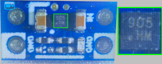
The board cuts power and turns a red led on when more than 5.5V are detected on the input side of the board. It cuts power too when less than ~3V are detected. The over voltage protection board supports input voltages up to 30V, so it is on the safe side even if the step down board (which sits before it) causes a short. The board can sustain a 2.5A load, with peaks of 5A, so it is again within the 2.1A load and 3A peak of the step down board.
The Step Up board converts the 5V from the step down board at J9 into +12V and -12V, which are then used on the cartridge slot ports and the FMPAC power connector.
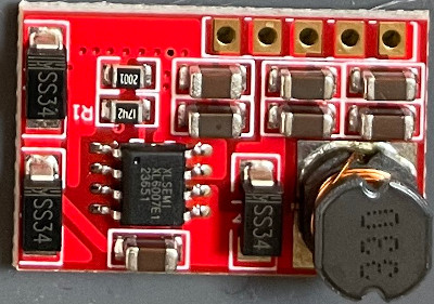
The board supports input voltages from 3.3V to 11V, within the margins of the over voltage protection board that provides the input voltage. On the current side, the board supports a peak 1.8A on the input and provides just a maximum of 700mA for the +12V and 150mA for the -12V.
The cartridge slot ports are protected by 50mA fuses to comply with the max 50mA for all slots MSX specification.
Follow these Build instructions in order to assemble the Omega DC Adapter board.


