lora development boards
1.0.0
This repository contains the design of a development board for the RFM95W-915S2. The PCB was designed using KiCad.
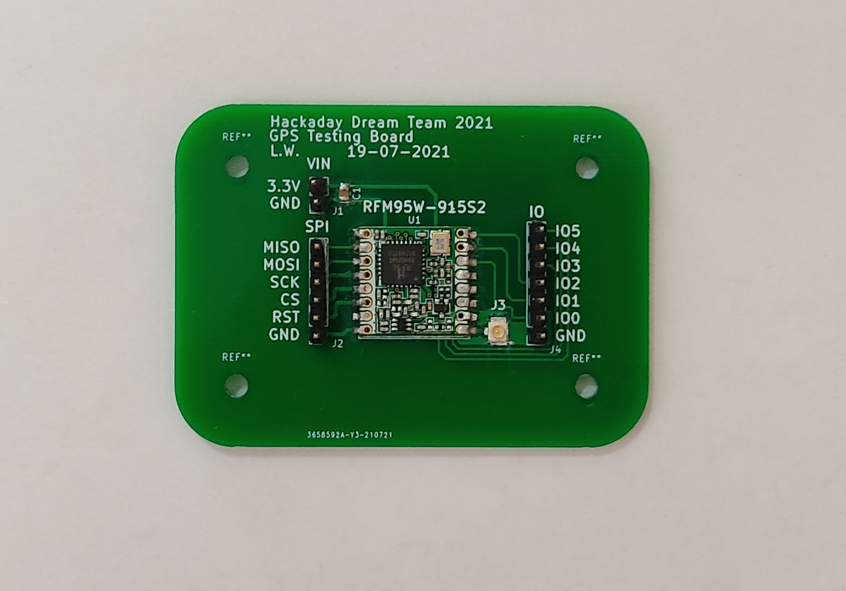
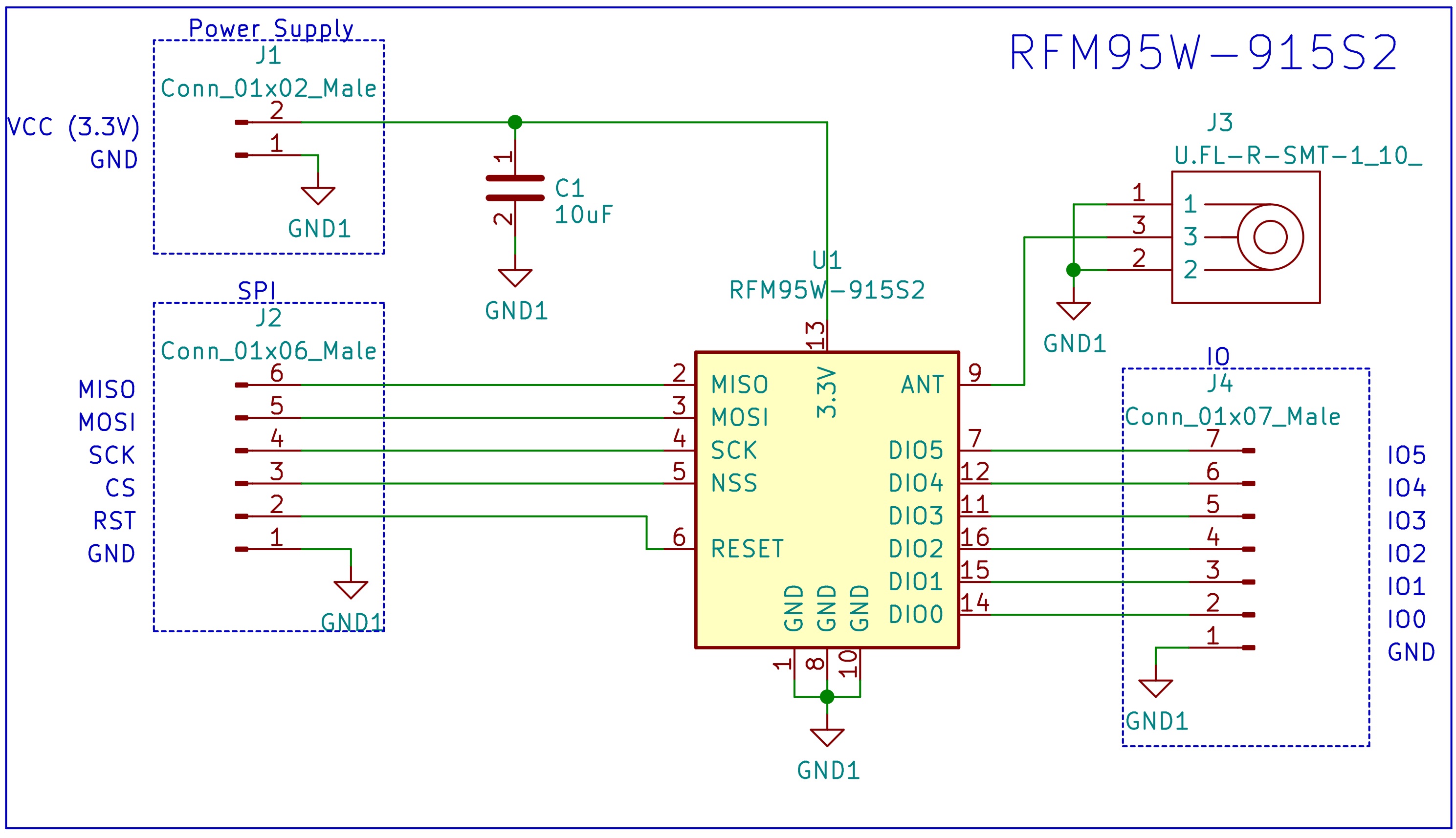
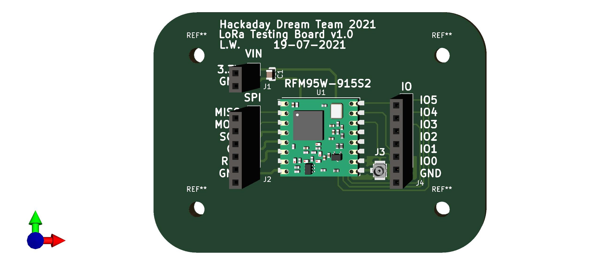
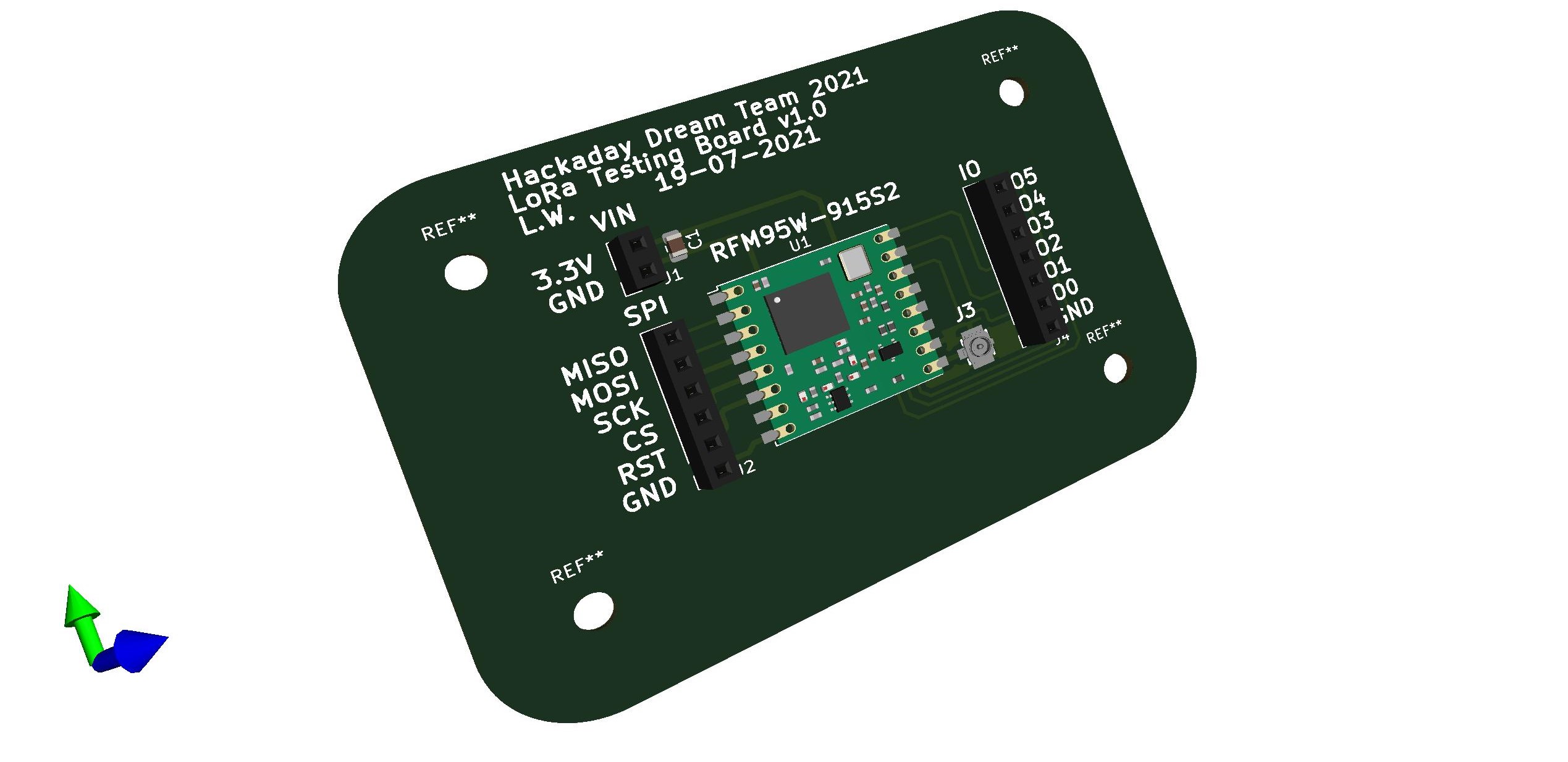
The RFM95W-915S2 Development board is a PCB that contains a RFM95W LoRa transceiver, a U.FL connector for the external antenna, a decoupling capacitor and a group of headers connected to the different pins of the transceiver. The transceiver can be used as a sender or a receiver.
Back to top
| Reference | Quantity |
|---|---|
| RFM95W-915S2 LoRa™ Transceiver Module 915MHz SMD | 1 |
| 10 µF ±10% 6.3V Ceramic Capacitor 0805 | 1 |
| U.FL (UMCC) Connector Receptacle, Male Pin 50 Ohm SMD | 1 |
| Conn Header 40POS 2.54 | 1 |
Back to top
Back to top
The webpage randomnerdtutorials.com has an amazing tutorial named ESP32 with LoRa using Arduino IDE – Getting Started, that tutorial contains detailed information about how to use the RFM95 with an ESP32 (the same microcontroller that was selected for our designs). I used the same firmware and connections provided by the tutorial.
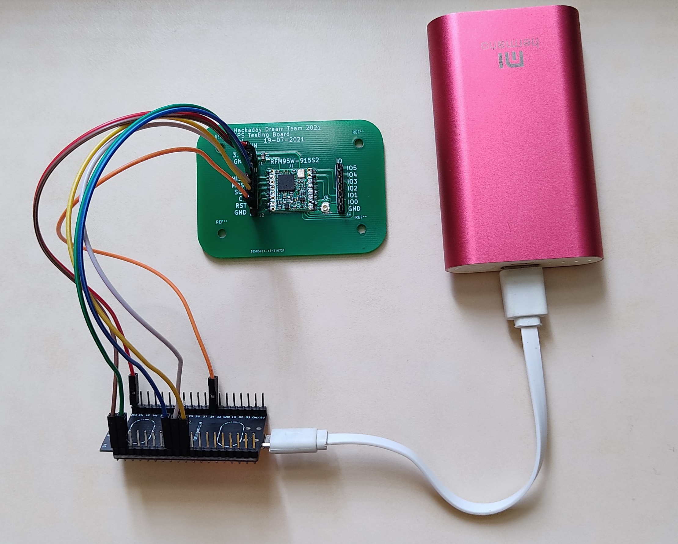
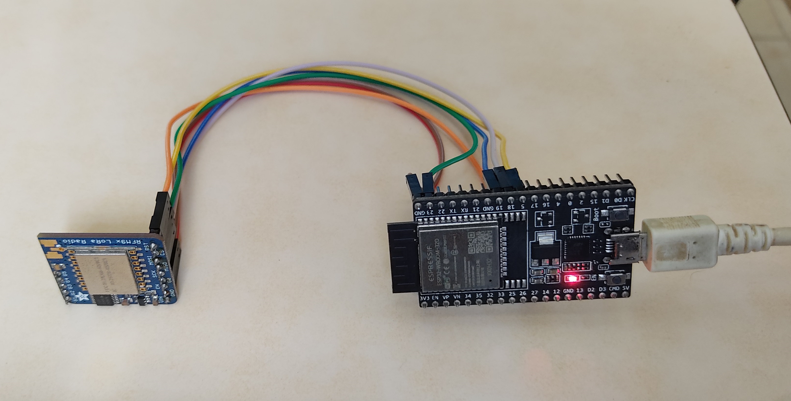
The test requires 2 transceivers, one of them will be used as a sender and the other as a receiver. In this case, one of the transceivers is the RFM95W-915S2 Development board and the other one is the RFM95W transceiver from Adafruit.
The connections are the following:
| ESP32 | RFM95W-915S2 Development Board |
|---|---|
| 3V3 | 3.3V |
| GND | GND |
| GPIO 14 | RST |
| GPIO 5 | CS |
| GPIO 18 | SCK |
| GPIO 23 | MOSI |
| GPIO 19 | MISO |
| ESP32 | RFM95W Board from Adafruit |
|---|---|
| 3V3 | VIN |
| GND | GND |
| GPIO 14 | RST |
| GPIO 5 | CS |
| GPIO 18 | SCK |
| GPIO 23 | MOSI |
| GPIO 19 | MISO |
This repository contains a folder named /Firmware/ that contains the project for the transceiver as a receiver and a sender.
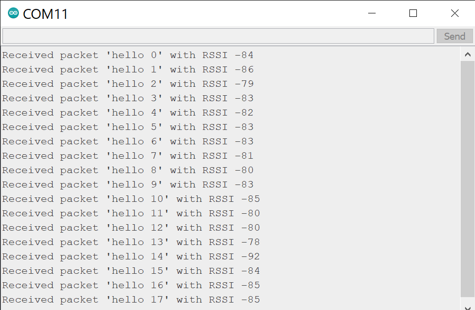
Both of the RFM95W Boards were used as a sender and receiver, the result was successful in both cases. During the test, one of the transceivers sends the package "hello counter", where the counter is a number that goes from 0 to 32767. The other transceiver receives the package and prints the message through serial.
Results visualized in the serial monitor from the receiver circuit:
For more information about the firmware visit the original tutorial for the RFM95W.
Back to top
Back to top


