another_esp8266_sensor_board
1.0.0
This repo contains build instructions for a multi-purpose esp8266 sensor device for home IoT projects.
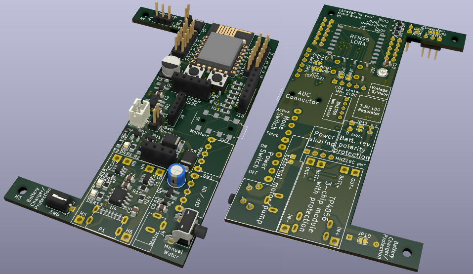 Board V5, partially populated. Image generated in KiCad.
This sensor board meets most of my home-automation hardware needs. It fits in a cheap, widely-available enclosure (no 3d printing required), and can be powered either by a Li-Ion battery (voltage-monitoring, charging, reverse-polarity, and protection circuitry included) or USB, with appropriate power sharing if the USB and battery are connected simultaneously. On the software side, I’ve kept things as high-level as possible: Tasmota for most usage scenarios; micropython where needed. Communication utilizes the MQTT protocol over Wi-Fi, or LORA (I use the board as both a remote LORA sensor, and as a LORA-MQTT bridge).
The board is designed for the following sensors, as well as motor/pump control (for automatic plant watering). GPIO pins remain easily-accessible, so this board can also be used as the basis for many other sensors.
The use of an esp8266 comes with some limitations, specifically around available GPIO, and only one ADC port. This means that not all potential functionality is available at the same time. Yes, these limitations could be overcome either with a port splitter, or by utilizing a different microcontroller such as an ESP32; however part of the fun for me was seeing how much I could do with only the esp8266, and the end result fits all of my use-cases.
 |
 |
|---|---|
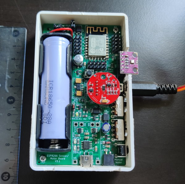
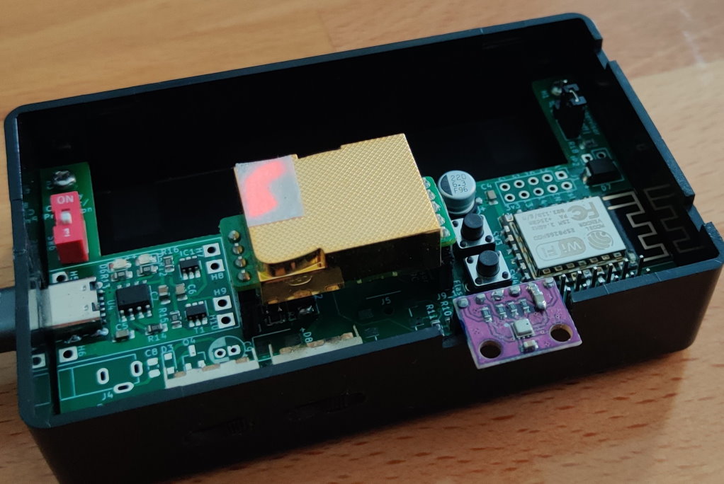
| V4, with BME280 (temperature, pressure and humidity), BH1750 (lux) and moisture (via the audio plug) sensors. Equipped for watering pump (bottom right); not currently connected. | V5, with the BME280 and MH-Z19C (CO2) sensors |
 |
|---|
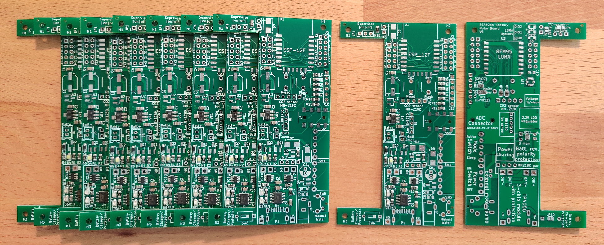
| A fresh delivery of V5 boards |
You could (should?!) use something else. I initially designed this as a way to learn about IoT sensors and circuit design/fabrication. I’ve stuck with it because it provides several advantages over off-the-shelf boards:
The board can be powered either directly from USB, or from a Li-Ion battery. Board V4 and earlier used micro-USB; V5 uses USB-C. The cutout on the left of the board is designed to accommodate a 1-cell 18650-battery case such as this (purchase link). The battery connector is a 2-pin JST-PH (2mm pitch), but if you prefer, just solder the wires directly to the connectors.
If both battery and USB are connected simultaneously, a power-sharing circuit ensures that only the USB powers the board. The battery is used in conjunction with a copy of the common 3-chip TP4056-based module for charging. There’s a switch provided if you’re not using a battery and want to bypass this circuitry (or if you don't want the battery to charge while USB is connected). The module includes protection for overcharge, over-discharge, overcurrent and short-circuit. Note that the overcurrent and short-circuit protection is bypassed for the rest of the board (not the battery) when USB is connected, and the power-sharing circuit is therefore active. The standard charging module doesn’t include battery-polarity protection, so I’ve also added that.
Battery voltage monitoring is available when either jumper JP5 (front) or JP6 (back) is bridged. This connects the positive battery terminal, through a voltage divider, to the esp's sole ADC pin. This connection is optional because the moisture sensor (and of course other sensors) also need access to the ADC. Due to this, it's clearly not possible to monitor both battery voltage and a soil moisture sensor at the same time with the V5 board.
Notes
There’s a dizzying range of possible LDO ICs to choose from. I settled on the XC6203P332PR due to its relatively high current output, and low dropout voltage. Board V4 had footprints for two alternative regulators, which I was planning to test for stability, but these weren’t needed and were removed in V5.
On PCB version 4 I paired two 1μF tantalum capacitors with the XC6203, per the datasheet. I had a capacitor fail on two of these boards after a few weeks of use, causing a short-circuit and lots of smoke (the boards were being USB-powered at the time). After reading tantalum horror-stories online, I decided to experiment with swapping them for ceramics on V5, and have experienced no further problems. I later discovered that the two failures were my fault: I fitted the parts in reverse! I’m sure there’s a good reason why the polarity-marker band on tantalums denotes the positive, while on aluminium capacitors and diodes it denotes the negative, but they tripped-up this newbie.
Conveniently, the XC6203P332PR is also compatible with the white ESP-12F adaptor boards. It’s smaller than the provided footprint, but can still be soldered onto it with little trouble. Make sure you remove the central zero-ohm resistor on the front of the board if using a board-mounted regulator.
I learned the hard way about the electrical-noise sensitivity of the ESP8266: on V3 of the board, it would reboot whenever the watering motor was activated. I overcame this in V4 with component repositioning (moving the motor to the far end away from the microcontroller), adding extra capacitors next to the motor connection, increasing power trace width vs signal traces, minimizing loops on the ground plane, and separating the motor ground-plane return path from the rest of the components.
The board is designed for an ESP-12F. I tend to flash the chip in a programmer board prior to soldering it on, just to check it's working.
When installed, it can be flashed in the normal way by connecting a USB-UART interface board to the appropriate pins.
| Pin# | Port | Board Connection | Resistor* |
|---|---|---|---|
| 1 | RST | Reset button | |
| 2 | ADC | ADC (moisture or battery) | |
| 3 | EN | Chip enable | Supervisor, or E-PU |
| 4 | IO16 | DeepSleep | |
| 5 | IO14 | I2C SCL, or SPI SCK | |
| 6 | IO12 | Moisture VCC, or SPI SDO-MISO | |
| 7 | IO13 | I2C SDA, or SPI MOSI | |
| 8 | VCC | ||
| 15 | GND | ||
| 16 | IO15 | LORA NSS | E-PD |
| 17 | IO2 | Onboard LED, & SPI SS | |
| 18 | IO0 | Flash button | E-PU |
| 19 | IO4 | Mode switch (GND: use sleep) | E-PU |
| 20 | IO5 | Water pump, or LORA DIO | E-PD |
| 21 | RXD | CO2 Tx | |
| 22 | TXD | CO2 Rx |
* Resistor attached to pin: I:Internal, E:External, PU:Pull-Up, PD:Pull-Down
There seems to be some online debates about the optimal way to connect RST to GPIO16 in order to use the ESP8266’s DeepSleep functionality. I’ve erred on the side of caution and added a diode between the two.
The ESP8266 is susceptible to brown-outs if the voltage is too low (a good explanation of this problem can be found here). In conjunction with the non-instantaneous increase in voltage from the regulator when power is first applied, this can lead to boot problems. To protect against this, I’ve included an optional voltage supervisor (TPS3839G33DBZ) which will only set the chip-enable pin high when voltage is above an appropriate threshold. However, I’ve yet to notice brown-outs being a problem, so I sometimes skip this component.
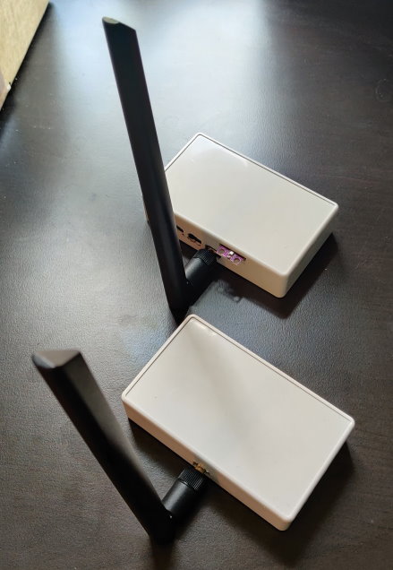 A pair of LORA-equipped devices in their enclosures
Combining an esp8266 with a LORA module is a stretch when it comes to available gpio. This board is designed to work with SX1276 LORA modules (example link), and leans heavily on the design from here, which minimizes needed ports by linking three of the LORA module's pins (DIO0, 1 and 2) to one esp8266 pin via three diodes (board footprints D9, D10 and D11 respectively). This DIO-sharing configuration needs special handling in software. However, for simple LORA communications only DIO0 is needed, so for my LORA boards to date I have bridged D9, and left D10 and D11 disconnected.
For testing, you can directly solder the common helical-wire antennas (often included with the purchase of a module) directly to the module's antenna pin. Range will suck, though. For better range attach a higher-gain antenna (I use 5dbi antennas bought here). I include an IPEX U.FL-R footprint at AE1. Alternatively, SMA edge-mounted connectors fit nicely on the edge of the board over footprint J5. These can be wired-up as follows (this example is using board V4, but the same will work for V5): top and bottom.
Notes
A single ADC is available on the esp8266, with a measurement range from 0V to 1V. For measuring higher voltages, a voltage divider is therefore needed. On board V5, the ADC can either be used for peripherals connected to the audio jack, or to monitor the battery voltage if either JP11 or JP5 is closed.
Connections via the audio jack go through a divider with R1=470 kΩ (component R7), R2=200 kΩ (component R8). This permits measurement of voltages up to 3.3V (3.3V is lowered to approximately 0.985V; calibrate the signal for higher accuracy).
The battery connection adds an additional 330 kΩ (component R10) resistor in series with component R7, leading to R1=800 kΩ. This increases the measurement range up to 5V.
I chose to use a 4-pole audio jack (model PJ313E) to connect the moisture sensors to the board. For now, only three of the four poles are connected; the fourth is a spare with an eye to future functionality. Starting from the base to the tip of the audio plug, the current connections are:
| Pole | Connection |
|---|---|
| 1 | GND |
| 2 | No connection |
| 3 | 3.3V (from GPIO12, via JP3) |
| 4 | To ADC via 3.3V voltage divider |
I've experienced one problem with my chosen socket (or maybe the combination of the socket and the plugs I use): by default, it's failing to make a connection to all four poles. This can be seen in the top image here, where the deepest contact-pin (Pole 4) isn't deflected. To fix the problem, I snipped/filed-off the protruding plastic front part of the socket (bottom image)
Small water pumps and the necessary flexible tubing are widely available. As discussed above, they're electrically-noisy buggers; hence why the connector for the pump is in the far corner of the board from the esp, and shielded behind two capacitors of its own. It's normally powered by gpio5, via an N-channel MOSFET, or can be manually operated with the optional button SW5.
For simplicity, and since the small pumps seem to be able to function over quite a wide voltage range, the pump is supplied with whatever voltage is currently powering the board (defined by the state of the power sharing circuitry): if USB is connected, it'll be 5V minus the forward voltage across diodes D2 and D8; if battery-powered, it'll be the battery voltage minus the D8 drop. In practice it really doesn't make much difference: slightly more water will be pumped during a given time when on USB vs battery-powered.
For the pump's board connection, there's a footprint for a DC-002 socket. I considered using a USB socket but decided that was misleading since the output voltage isn't always the 5V that one would expect from USB. On the board pictured above, I skipped the power-jack socket and simply connected a double pin-header socket instead.
I chose this project box because it's cheap, widely-available, and just the right size for the pcb and an 18650 battery.
8mm M2.6 screws are needed to attach the board to the box, such as these.
| Property | Module | Board Connection | Datasheet | Purchase Link* |
|---|---|---|---|---|
| Temperature, pressure, humidity | BME280 | Direct (2.54mm headers) | Link | |
| Lux | BH1750 | Direct (2.00mm headers) | Link | AliExpress |
| CO2 | MH-Z19C | Direct (2.54mm headers) | Link | AliExpress |
| Moisture | “Capacitive soil moisture sensor V1.2” | Audio plug | Link (older version) | AliExpress |
*I've purchased from those links in the past, but they're provided with no guarantee. I also don't plan to update them when they inevitably expire.
This is a very handy temperature, humidity and pressure sensor. With the sensor's current mount point, it sits partially outside of the enclosure. I find this convenient because I don't have to worry about airflow within the box. If the current geometry offends you, or you need a more robust device where the sensor won't risk getting damaged, consider a redesign on the connection point, or choose an alternative sensor with a built-in cage.
You might find that the soldered pins get in the way of closing the enclosure lid properly. If this is the case you can trim them prior to soldering, like I've done here.
The sensor can communicate by I2C or SPI; most people seem to use I2C, for which you need to make no board alterations. If you want the SPI interface, close a couple of solder bridges on the rear to connect the additional pins. On board V5, one of these connections also powers the moisture sensor, so alterations would be needed if you want to run both the BME280 (with SPI interface) and a moisture sensor concurrently.
Notes
This is a simple and reliable photodiode, combined with an I2C interface. You can buy it in various form-factors, with the light-ball version being particularly convenient for our purposes. Trim-down the plastic parts of the built-in connector, and this can now plug directly into a standard 2mm-pitch pin header, as included on board V5. The light ball can be popped off the sensor and directly mounted into the top of the enclosure.
Notes
This is the priciest sensor I use, but I think it's worth it vs the cheaper VOC alternatives. It communicates over the UART bus (so esp8266 pins Rx and Tx). You therefore want to ensure the sensor isn't connected if you're trying to flash the ESP or use its serial interface.
To use the MH-Z19C on the board V5, you need to connect two solder bridges on the rear. In hindsight I can't think of a good use-case when you wouldn't want those bridged, so I'll probably just swap the pads out for continuous traces on any future version.
Notes
In order to stop the moisture sensor running constantly and draining the battery, it's powered directly by gpio12. Bridge the right pad of JP3 to the centre pad to make that connection. It doesn't draw much current, so I've had no problems directly powering the sensor directly from a gpio pin. If it turned out to be a brown-out/stability issue in the future, this connection would need to be replaced by a MOSFET.
The board was designed in KiCad, and manufactured by JLCPCB. KiCad files and the information required by JLCPCB are provided in the board_v* directories.
Please be understanding with the schematic; I know it's ugly and desperately in need of splitting into multiple parts. Remember, this is my first PCB design!
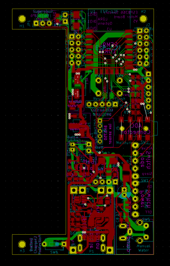
Board V5 layout
For convenience, I use Tasmota for all devices where possible. Tasmota can't handle LORA, so for these devices I use micropython.
Web install link
Make sure you install the "sensors" version of the tasmota image.
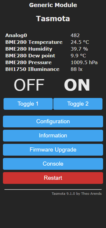
Here are some Tasmota screenshots from the V4 device pictured at the top of this readme.
 |
| 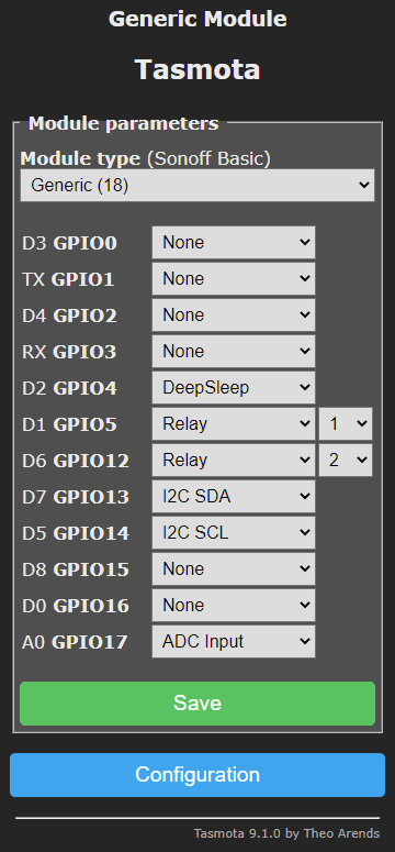
Here are the main settings I changed from their default in the control interface. Read about these and other settings here.
Notes
POWER2 ON commandOutput Hi rather than Relay 2. It'll then be set high early in Tasmota's boot process, and still switch off when the microcontroller goes into deep sleep.Look here for my LORA micropython software and instructions: https://github.com/brev-dev/LORA_esp8266_sensor_MQTT_bridge.
Although not covered by this repo, here are some quick notes on where these devices sit in my full home setup.
My home setup is designed to achieve these goals:
To enable temperature control in each room, the radiators are plugged into Tasmotized esp8285 smart plugs.
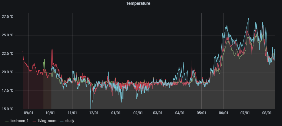
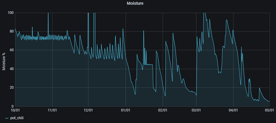
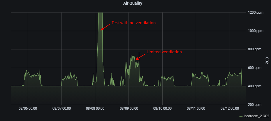
The "hub" is a Raspberry Pi 4 equipped with Mosquitto, NodeRed, InfluxDB, and Grafana. My NodeRed flows could probably be simplified by replacing much of it with, for example, HomeAssistant, but I haven't looked into that. The combination of InfluxDB and Grafana is used to store and visualize the historical data (examples below), along with the "MQTT Dash" app on our phones to monitor the current status and change temperature and moisture trigger levels. The rpi software stack utilizes Docker and IOTStack for ease of configuration and maintenance. Andreas Spiess has some great videos on the topic, including: #255, #295, and #352.