ESPHomePCPowerControlHomeAssistant
v1.0.1
This project contains remote PC power control via HomeAssistant and ESPHome ESP8266/ESP32 boards.
I use this project to power my PC based NAS remotely on and off via Home Assistant as alternative to Wake-On-Lan (WOL) which has known limitations.
power-off/suspended/hybernate (Behavior short press power button).shutdown/suspend/hybernate of the operating system (Behavior short press power button).Youtube video:
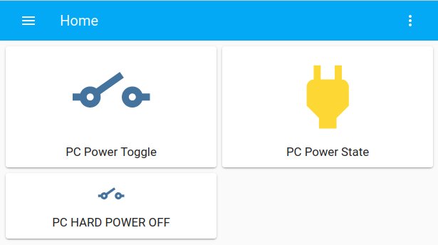
Homeassistant screenshot:
Wake-On-Lan (WOL) is intended to turn computer power on remotely via Ethernet by sending a so called magic packet. This has several known limitations which are not applicable with this ESP project:
wake a PC from suspend or power-off state. There is no shutdown/suspend functionality.sleep state, a SSH connection to the remote PC can be made for example by executing pm-suspend command (Install via sudo apt install pm-utils), reference Ubuntu pm-action documentation. Disadvantages:
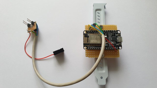
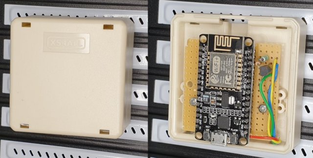
The hardware consists of an ESP8266 or ESP32 and two IO pins, mounted on a PCI metal plate (see picture below). In my case I used an ESP8266 NodeMCU board. Theoretically any ESP8266 or ESP32 board can be used for this project.
My NAS is based on an Intel Core I7 ASRock Z97 ATX motherboard and contains standard 2.5mm 2x5 male headers:
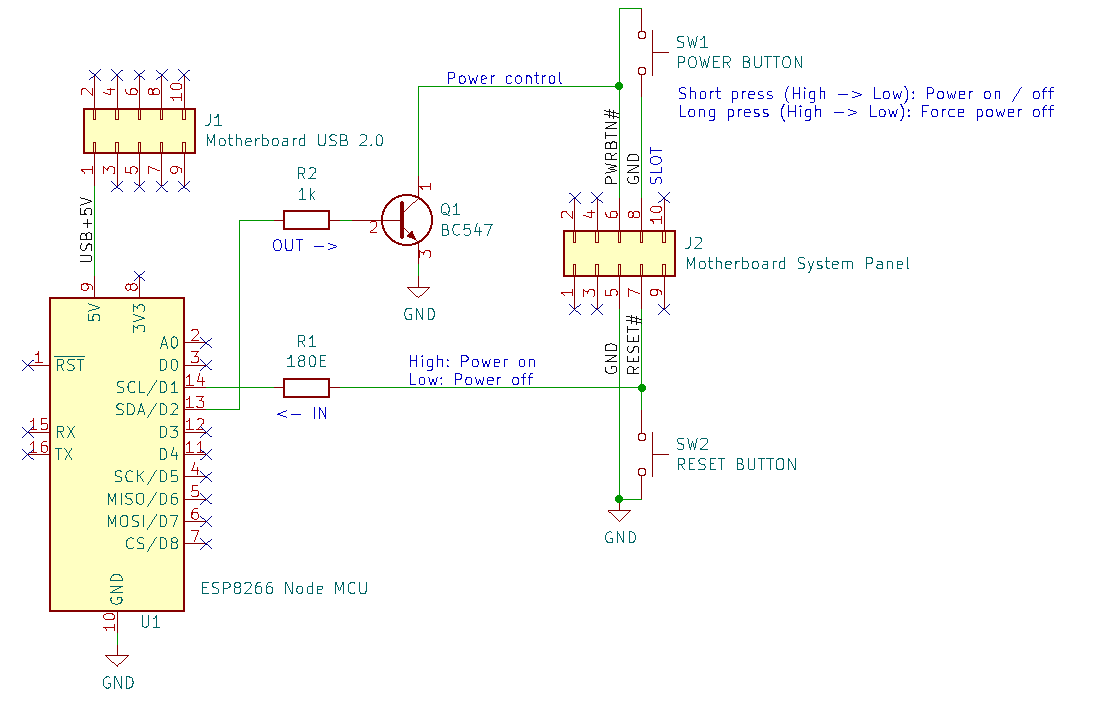
ATX header USB 2.0:
Header J1 pin 1 constant +5V power on pin 1, even when the PC is power-off and is used to power the NodeMCU. The ESP8266 or ESP32 is powered via an on-board 3V3 regulator.
ATX header System panel:
Header J2 contains the power, reset and GND pins:
Power button pin 6.
Reset button pin 7.
GND pin 5.
Pin D1 is used to read the power status from the reset pin: High is on, Low is off. Resistor R1 is used to minimize current when the IO pin is accidentally set to output.
Pin D2 is used to pull the power button low to generate a short or long press. Transistor Q1 is used for secure isolation between ESP8266 and motherboard.
Warning: All ATX and ESP pins must be operating at 3V3.
A DIY breakout PCB can be mounted at the system panel header to connect power button SW1 and reset button SW2.
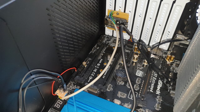
There is sufficient space in an ATX computer case to mount the ESP board. However, the computer case is metal shielded, so the WiFi distance to the base station reduces. It is recommended to place the ESP outside the computer case when the WiFi connection is unstable or distance too low. An ESP32 may result in different WiFi connection stability, but overall it depends on the environment.
ESP8266 PCB mounted at the back of the PC case:
The ESPHome application firmware can be updated via USB connection (virtual serial port) or WiFi OTA (Over The Air update).
Updating the firmware via WiFi is enabled when configuring ota in the .yaml file. This requires a WiFi connection between host computer and ESP. OTA update does not work when the login from ESP to WiFi base station fails due to incorrect WiFi credentials. In this case an update via serial is required or via ap fallback as configured in the .yaml file.
The ESPHome application consists of the two Yaml files. One configuration file and a second secrets.yaml to store passwords.
Documentation:
Configure the following files:
platform and board.Please refer to ESPHome documentation for more information about ESPHome YAML configuration.
Connect USB cable to ESP8266 or ESP32 board and enter the following commands. (Examples are tested on Ubuntu). For more information, refer to ESPHome.io.
# Clone this repository
$ git clone [email protected]:Erriez/ESPHomePCPowerControlHomeAssistant.git

# Install Python3 virtualenv
$ sudo apt install python3-virtualenv

# Create virtualenv
$ virtualenv venv

# Activate virtualenv
$ source venv/bin/activate

# Install ESPHome
$ pip install esphome

# Optional: Install platformio updates
$ platformio platform update
$ platformio upgrade

# Optional: Add user permission serial port
$ sudo usermod -a -G dialout <USERNAME>
$ sudo reboot now

# Check ESPHome installation
$ esphome --help

# Optional: Compile program without upload
$ esphome compile pc-power.yaml

# Upload program to ESP8266 or ESP32
$ esphome run pc-power.yaml

# Select serial port or WiFi to upload application

# Check logs
$ esphome logs pc-power.yamlThis section describes Home Assistant configuration.
Configuration | Integrations: Add Integration: ESPHomesecrets.yml | esphome_api_password.Add PC power integration to a dashboard via raw edit:
title: Home
views:
  - title: PC
    path: pc
    badges: []
    cards:
      - type: button
        entity: switch.pc_power_toggle
        show_name: true
      - type: button
        tap_action:
          action: none
        entity: binary_sensor.pc_power_state
        hold_action:
          action: none
      - type: button
        tap_action:
          action: toggle
        entity: switch.pc_hard_power_off
        icon_height: 40px
        show_state: false
        show_name: true
show_icon: trueRestart Home Assistant and ready to go!
The ESPHome YAML file format changed with ESPHome version 2024.6.0. The old format generates errors like:
$ esphome compile ESPHomePCPowerControlHomeAssistant/pc-power.yaml
INFO ESPHome 2024.9.2
INFO Reading configuration ESPHomePCPowerControlHomeAssistant/pc-power.yaml...
Failed config

ota.unknown: [source ESPHomePCPowerControlHomeAssistant/pc-power.yaml:27]

  'ota' requires a 'platform' key but it was not specified.

and:

Failed config

switch.gpio: [source ESPHomePCPowerControlHomeAssistant/pc-power.yaml:30]

  Pin 4 is used in multiple places.
In this case, please update to the new file format in this project.
switch.pc_power_button to switch.pc_power_toggle.switch.pc_power_button_long_press to switch.pc_hard_power_off.switch.pc_power_sense to switch.pc_power_state.

