pic18f47q10 crc with memory scanner
2.0.3

This example demonstrates the use of CRC peripheral in PIC18F47Q10 microcontroller. CRC module in PIC microcontrollers is hardware implemented checksum generator which computes 16-bit CRC with programmable polynomial. It is coupled with memory scanner for faster CRC calculations. The memory scanner can automatically provide data to the CRC module This example uses CRC-16-CCITT standard parameters. This demo calculates the CRC of the program memory and store it in the EEPROM area of the controller after programming the device for the first time. On the subsequent power-ups, the device computes the flash CRC at startup and checks it against the CRC stored in EEPROM area. In case of mismatch the program execution is indicates CRC error. This CRC checking can be scheduled periodically during device operation to ensure flash integrity.
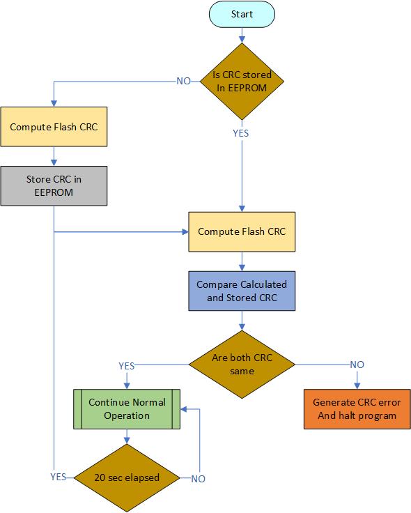
Figure 1: Program Flowchart
With full program and debug capabilities, the PIC18F47Q10 Curiosity Nano evaluation kit offers complete support for the new design. The kit uses the MPLAB® X IDE and MPLAB® Code Configurator (MCC), providing access to the Intelligent Analog and Core Independent Peripherals on the PIC18F47Q10.
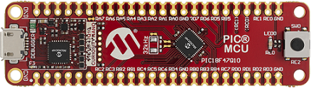
Figure 2: PIC18F47Q10 Curiosity Nano board
Microchip’s free MPLAB X IDE, compiler and MPLAB Code Configurator (MCC) graphical code generator are used throughout the application firmware development to provide an easy and hassle-free user experience. Following are the tool versions used for this demo application:
Note: For running the demo, the installed tool versions must be the same or later. This example is not tested with previous versions.
Start by creating a new Project and open MCC
Configure the hardware peripherals
Open the Clock Control setup present under "System" dropdown menu in the Project Resources tab.
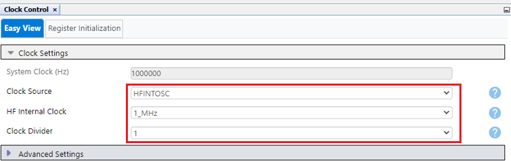
Figure 3: Clock Control
Open the Configuration Bits setup present under "System" dropdown menu in the Project Resources tab.
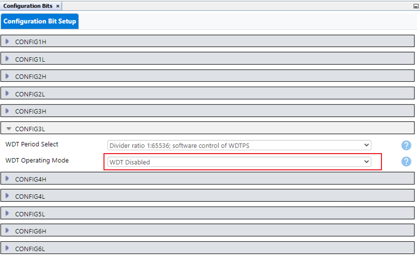
Figure 4: Configuration Bits
Add CRC, UART2, TMR0 and NVM peripherals to the project.
Make sure to add peripherals present under Drivers dropdown menu in Device Resources tab.
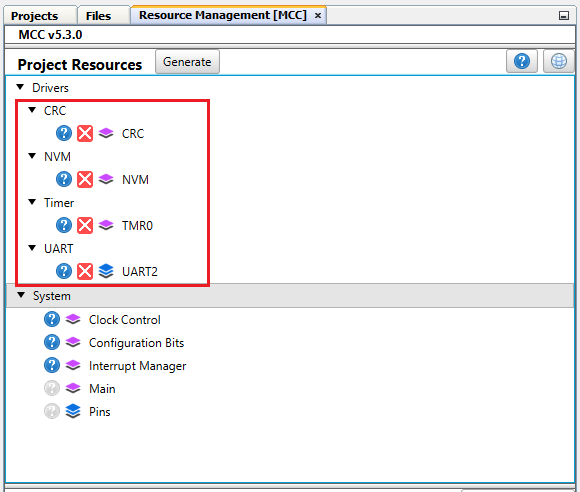
Figure 5: Peripherals
Configure the CRC peripheral
Verify that CRC is enabled
Verify that Use Pre-defined Polynomial is enabled
Select CRC-16-CCITT from list of Pre-defined Polynomial
Set the Seed value to 0xFFFF
Set Augmentation Mode to data not augmented with 0's
Set Data Word Width (bits) to 16 (As Flash memory data width is 16-bits)
Verify that Scanner is enabled (We will use scanner to fetch data from memory)
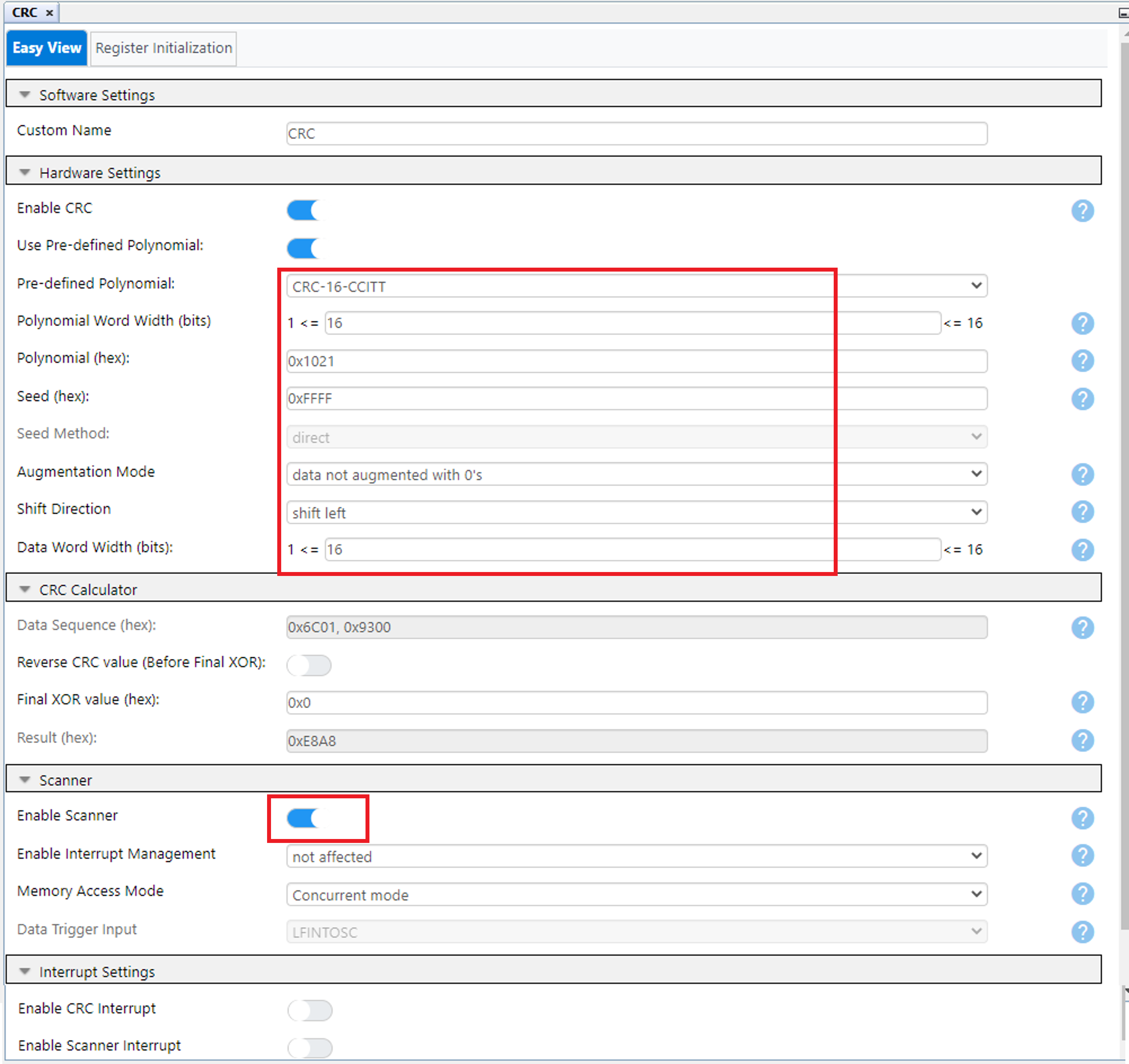
Figure 6: CRC Configuration
Verify that Generate EEPROM APIs is set (We will use these APIs to write EEPROM data)
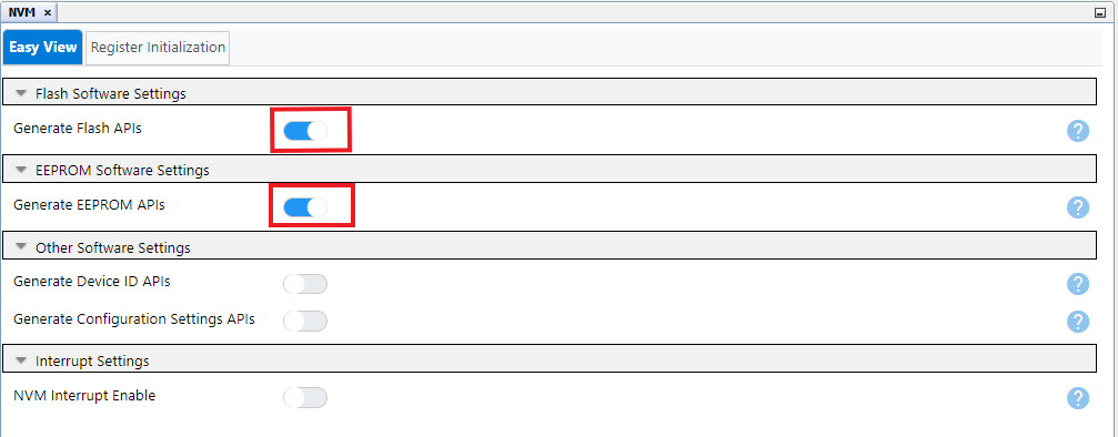
Figure 7: Memory Configuration
In this demo, UART2 is used to transmit data on the terminal window to display the stored and computed CRC value as well as the error message if there is any mismatch in the CRC is detected.
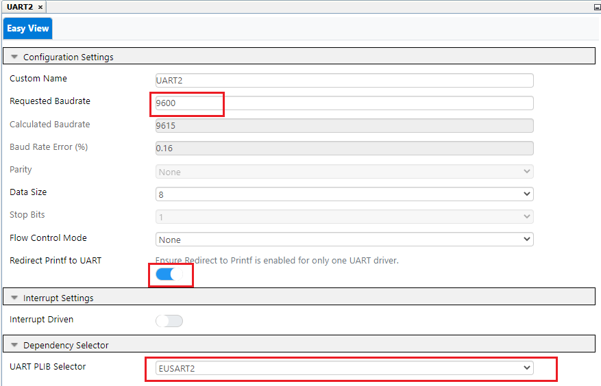
Figure 8: UART2 Configuration
In this demo Timer 0 is used to generate a periodic event for checking the CRC of the program memory. Timer 0 period can be adjusted to change the CRC calculation frequency.
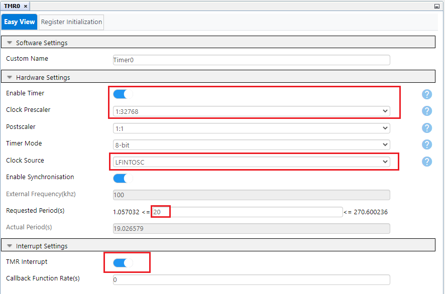
Figure 9: Timer 0 Configuration
Configure the pins used on the device
Set RE0 as output pin using pin Manager: Grid View. LED is connected to pin RE0.
Select RD0 as EUSART2: TX2 output.
RB7 used for RX2.
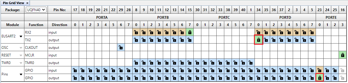
Figure 10: Pin Manager: Grid View
Add custom name to the RE0 output pin as LED, using Project Resources → System → Pins. Check the "Start High" check box for LED pin RE0 for turning off the LED.
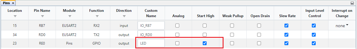
Figure 11: Pin Manager
Open main.c file.
Steps to calculate flash CRC using MCC generated APIs:
CRC_SetScannerAddressLimit(START_ADDRESS, END_ADDRESS);
(Start address used in this demo is 0x00000 and end address used is 0x7FFE. So total block size of the memory used for CRC calculation is 32Kb.)
Note: If the program size exceeds 32Kb then increase the block size by changing the End address
CRC_StartScanner();
while(CRC_IsCrcBusy() || CRC_IsScannerBusy());
CRC_GetCalculatedResult(false,0x00);

Figure 12: Program the device
//#define ERASE_EEPROM_CRC in the code, to erase the EEPROM location, which stores the CRC. This makes sure that there isn’t any incorrect or earlier calculated CRC value stored previously at that location. Build the project and program the device. Observe the message displayed on the terminal window.(Any terminal emulator such as MPLAB Data Visualizer can be used. Set baud rate as 9600.)
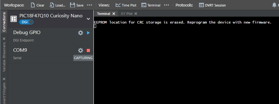
Figure 13: EEPROM erase message
#define ERASE_EEPROM_CRC. Build the project and program the device.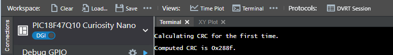
Figure 14: First Time CRC calculation
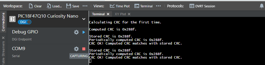
Figure 15: Periodic CRC
Note: CRC in Figure 15 is computed using compiler v2.41 with -0 optimization level.
CRC module is a hardware implemented checksum generator which can compute 16-bit CRC with programmable polynomial. It also uses a memory scanner feature which provides an automatic flash read for CRC calculations. Configuring the CRC module is easy using the MCC GUI. Apart from the module configuration, MCC generates ready to use APIs, for hassle free calculation of the CRC of the program memory, using CRC and memory scan hardware peripheral in the PIC microcontrollers.


