dspic33ck power pwm multi channel synchronization
1.0.0

Multi-Channel PWM Synchronization Across PWM Groups
Learning how to use the High Resolution PWM Module of dsPIC33C MP devices, Lab 5: Code example for dsPIC33CK and dsPIC33CH devices introducing the basic configuration of the high-resolution PWM module using three PWM generator channels generating three multi-phase PWM waveforms
Please always check for the latest data sheets on the respective product websites:
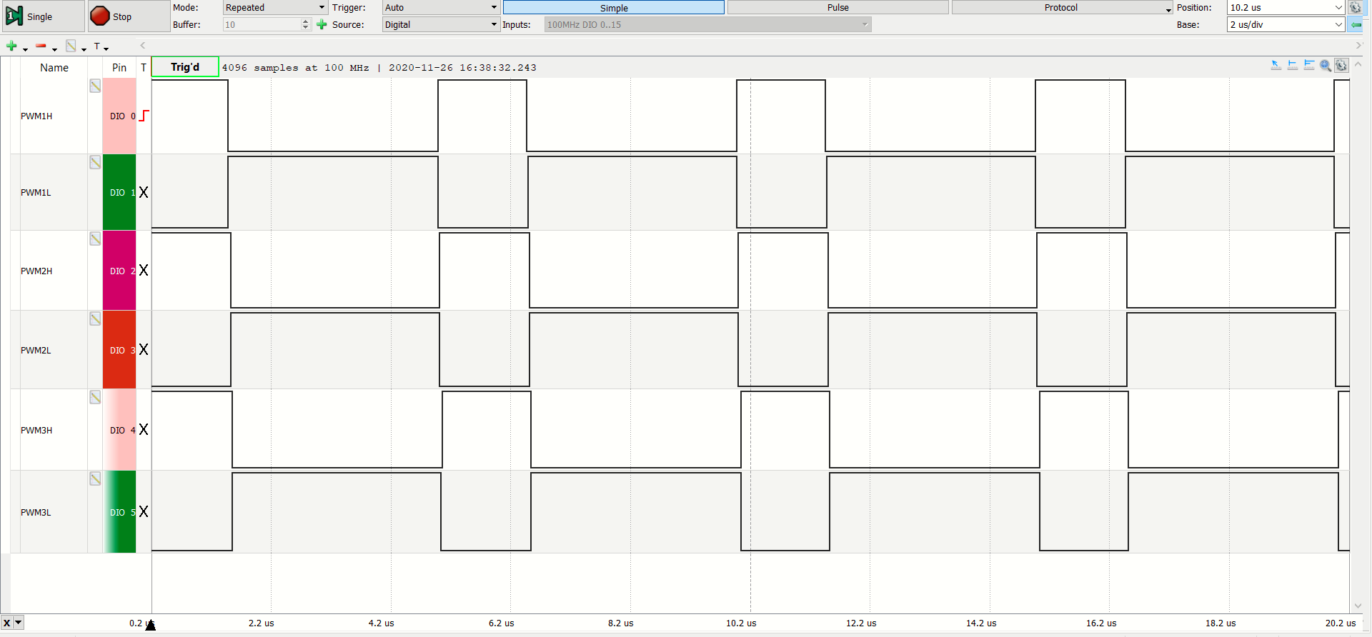
After the device has been programmed and the MCU starts up, PWM generators #1, #2, and #3 are generating three complementary pairs of 200 kHz and 30% duty cycle PWM waveforms at the PWM1H/PWM1L, PWM2H/PWM2L and PWM3H/PWM3L outputs respectively. These three complementary pairs of PWM waveforms are in-phase to each other.
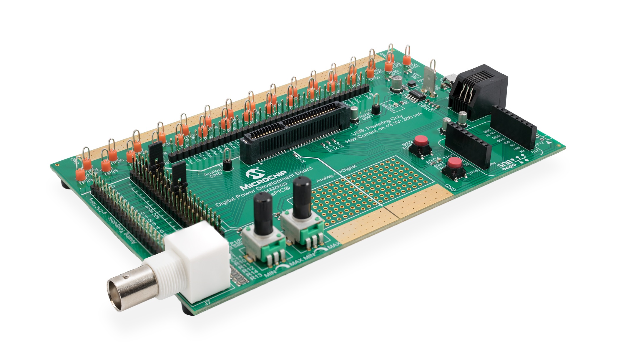
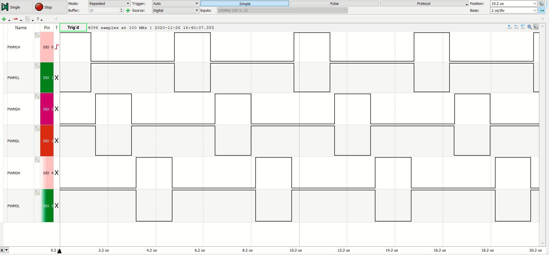
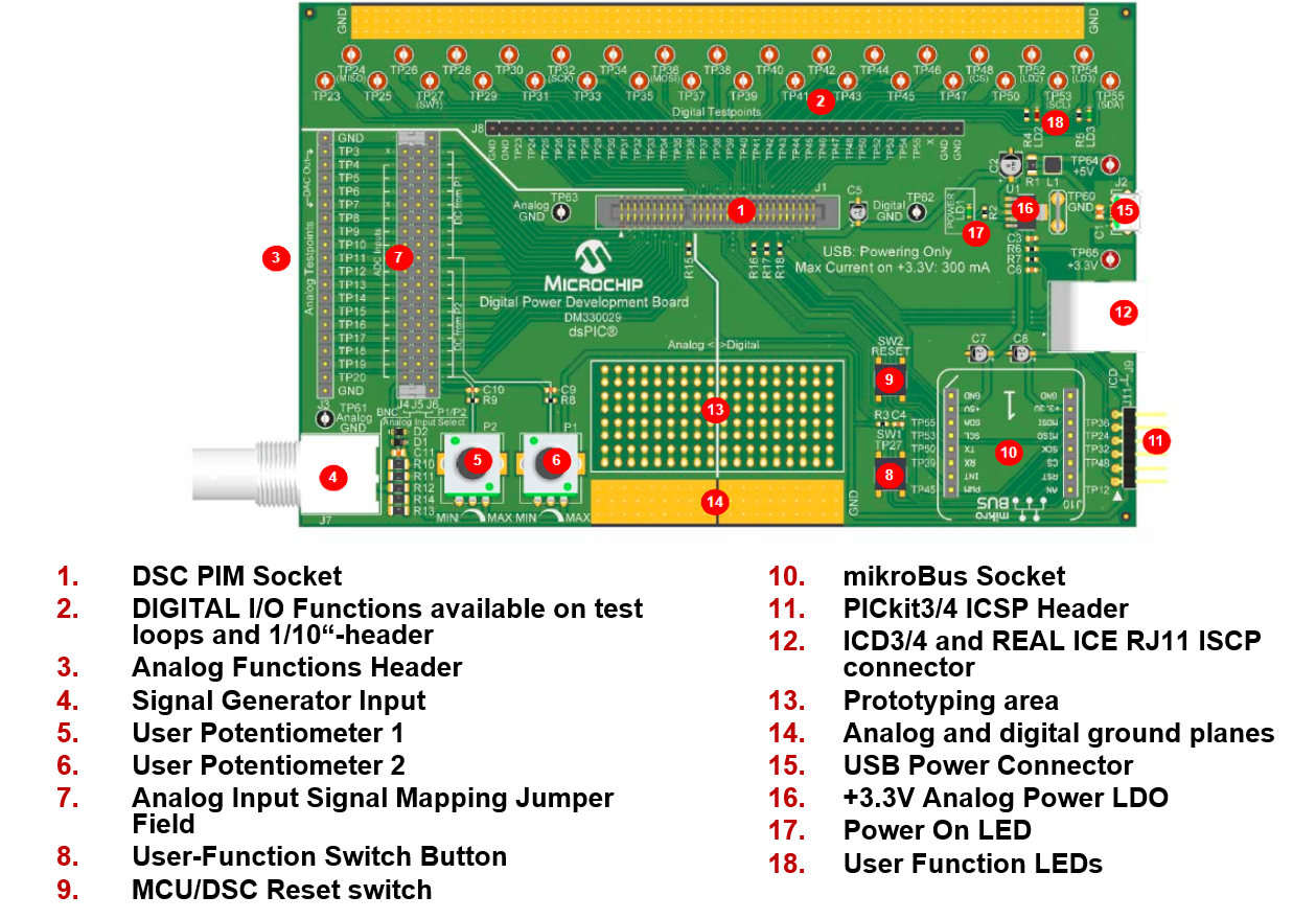
By pressing the on-board push button USER on the Digital Power Development Board, the three in-phase system is changed to a three-phase PWM system with a phase angle separation of 120 degrees, where the PWM2H/PWM2L pair is advanced by 120 degrees from PWM1H/PWM1L and PWM3H/PWM3L is advanced by 120 degrees from PWM2H/PWM2L. The system is toggled from in-phase PWMs to multi-phase PWMs with the USER switch.
Please refer to section FIRMWARE QUICK-START GUIDE below for more information on the initialization process and code structure.
This code example builds on previous code examples showing how to use Microchip Code Configurator (MCC) to set up device clock domains. Although MCC also supports configuration tools for the High Resolution PWM module, PWM configuration in this example builds on generic peripheral drivers to help users better understand the peripheral architecture and key aspects of specific configurations and operating modes. In each PWM example code project the PWM configuration procedure is located in the user file pwm.c, where each register bit required to achieve/enable the specific function or mode of interest is set and its function described with comments. Once users are familiar with the architecture, features and capabilities, both configuration options (generic peripheral library or MCC) may be used.
The project contains four sub-directories
On the hard drive, main.c/h are located in the MPLAB X project directory. All other user files, incl. peripheral drivers, are located in the sub-directory sources. Files generated by MCC are always located in their own sub-directory mcc_generated-files
The PWM peripheral driver files p33c_pwm.c/h provide data structures representing the Special Function Register (SFR) sets of PWM generators and the PWM base module. These 'virtual' PWM objects are used to load, read and modify PWM generator configurations without the need for hard-coded instructions, which would make the code hard to migrate from one peripheral to another or even across devices.To simplify PWM configurations, in these examples, each register is reset to a known default state before the user configuration of interest is set. Thus, only the register setting which really matters for a certain features/function are shown.
To learn more about the generic PWM driver, its supported features and intended use cases, please read the comments inside p33c_pwm.c.
This code has been written to automatically start up and perform the function of interest. Please read the demo instructions on top of file main.c to learn more about the code example, test points, expected signals and demo mode operation.
© 2020, Microchip Technology Inc.


